CONNECTING ELECTRICAL WIRING
21-4 ELECTRICAL CONNECTING TO OUTDOOR UNIT
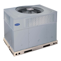
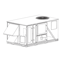
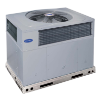
21.4.1 Description of Electrical Connections of Side Discharge Outdoor Unit
1. Remove the screw fixing service door.
And remove from unit.
2. Connect power cable to electrical box of outdoor unit
as per caution - field electrical wiring.
3. Connect control cable to electrical box of outdoor unit
as per caution - field electrical wiring.
4. Route wires from disconnect through openings provided
and into the unit electrical box.
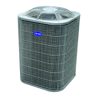
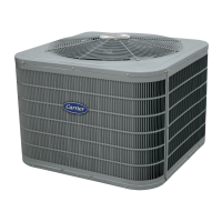
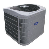
21.4.2 Description of Electrical Connections of Top Discharge Outdoor Unit
Power Wiring Control Wiring Corner Cover
1. Remove the screws at the side of the corner cover. Slide corner cover down and remove
from unit.
2. Connect power cable to electrical box of outdoor unit as per caution - field electrical wiring.
3. Connect control cable to electrical box of outdoor unit as per caution - field electrical wiring.
4. Route wires from disconnect through power wiring openings provided and into the unit
electrical box.

 Loading...


