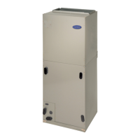
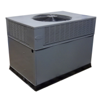
FB, FE, FF1E, FFM, FG, FH, FJ, FMA, FT, FV, FX, FY, FZ, F54, PF: Service and Maintenance Instructions
Manufacturer reserves the right to change, at any time, specifications and designs without notice and without obligations.
12
The ECM/ICM motor used with this product contains two parts: the
control module and the motor winding section. Do not assume the motor
or module is defective if it will not start. Go through the steps described
below before replacing control module, Easy Select Board or entire
motor. The control module is available as a replacement part.
If Motor Turns Slowly:
1. It is normal operation to run noticeably slower if G terminal is not
energized in cooling or heat pump heating modes.
2. Attach blower access panel. Motor may appear to run slowly if
access panel is removed.
If Motor Does Not Run:
Turn power off, wait five minutes and check the following:
1. With power turned off, check 5A fuse on Easy Select Board.
2. Check all plugs and receptacles for any deformation or corrosion
that could cause bad connections. Be sure plugs are fully seated.
Turn power back on and check the following:
3. Check for 24VAC on SEC1 and SEC2. If no voltage is present,
check transformer.
4. Verify that approximately 230VAC is present at motor.
5. Verify low voltage control signals to motor according to procedure
below.
Use following procedure to check low voltage signals:
The ECM motor in these fan coils receive low voltage signals from the
Easy Select Board through the wiring harness assembly. The
combination of pins energized at the motor determines the speed the
motor will run. The procedure below isolates the fan coil from all
external devices such as a thermostat, condensing unit, humidifier or
electronic air cleaner. There is also a specific troubleshooting example to
demonstrate the process. Table 6 provides information needed to verify
that the correct voltages are present at the motor and the Easy Select
Board.
THERMOSTAT:
1. Remove all thermostat and accessory wires from Easy Select
Board.
2. On Easy Select Board, jumper screw terminals (1 at a time): R-G,
R-Y/Y2, R-Y1, R-W1, R-W2. If motor runs in all cases, check
thermostat outputs. Thermostat wires may be broken, or thermostat
may be miswired, configured incorrectly, or defective. If the motor
does not run, or runs in some cases, but not others, continue this
procedure to check wiring harness and circuit board.
WIRING HARNESS:
1. Remove 16-pin/4-pin plug from motor.
2. Check for appropriate voltages on 16-pin/4-pin connector with
screw terminals jumpered (Table 3).
3. If signals check correctly, and motor does not run, inspect wiring
harness for loose pins or damaged plastic that could cause poor
connections.
4. If connections are good, either control module or motor is
defective.
5. If proper signals are not present, check circuit board using
procedure below:
6. If the unit contains a motor signal translator box (16X4), repeat
these steps with the connections on these connectors.
12-PIN PLUG (PL-1) ON EASY SELECT BOARD:
1. Completely disconnect wire harness from Easy Select Board.
2. Jumper the screw terminals one at a time; R-G, R-Y/Y2, R-Y1,
R-W1, R-W2 and check for appropriate voltages on the Easy Select
Board pins. If proper signals are not present, replace Easy Select
Board. If proper signals are present at the pins and not at 16-pin
connector to the motor, the wiring harness is defective.
TROUBLESHOOTING EXAMPLE:
Motor is not running on a call for heat pump heating after jumpering the
Easy Select Board screw terminals as described in Thermostat section
above.
With all thermostat wires removed from Easy Select Board, place a
jumper wire between R and Y/Y2 low-voltage screw terminals on the
Easy Select Board.
1. Check Table 6 for pin number on 16-pin connector associated with
the Y/Y2 signal. The correct pin is No. 14. The far right column of
the table shows that (-)12VDC should be present between Pin No.
14 and Pin No. 1 (common) on the 16-pin connector.
2. Set meter to read DC voltage. Place meter leads between Pins No. 1
(common) and No. 14 and check for (-)12VDC. If signal is present,
the problem is in the module or motor. If signal is not present, the
problem is either in wiring harness or Easy Select Board.
These steps can be repeated for other modes of operation.
To check Easy Select Board:
1. Leave jumper wire in place between R and Y/Y2.
2. Check Table 6 under “Volt Meter on Easy Select Board Plug”
column and row for Pin No. 14 on motor plug to see pin number on
Easy Select Board that should have voltage. The correct pin is No.
2. The column on far right will show voltage that should be present
between Pin No. 2 and Pin No. 9 (common).
3. Place meter leads between Pins No. 2 and No. 9 on Easy Select
Board and check for (-)12VDC.
4. If voltage is present, the wiring harness is bad. If not, the Easy
Select Board is bad.
Verify Motor Winding Section:
Before proceeding with module replacement, check the following to
ensure motor winding section is functional. With control module
removed and unplugged from winding section:
1. The resistance between any two motor leads should be similar.
2. The resistance between any motor lead and the unpainted motor end
plate should be greater than 100,000 ohms.
If motor winding fails one of these tests, it is defective and must be
replaced.
Accessories
AUXILIARY TERMINALS—The AUX and HUM terminals on the
Easy Select Board are tied directly to the G terminal, and provide a
24VAC signal whenever the G terminal is energized (Fig. 10). During
Superdehumidify mode, the G signal is not present and the auxiliary
terminals are not energized. If the installation includes the use of this
operating mode, do not use these terminals to control accessories. See
Electronic Air Cleaner and Humidifier sections for further information.
ELECTRONIC AIR CLEANER CONNECTIONS—The AUX1 and
AUX2 terminals are not always energized during blower operation, as
described above. When using an electronic air cleaner with the FV4 fan
coil, use an Airflow Sensor or Airflow Verification switch. The airflow
sensor turns on the electronic air cleaner when the fan coil blower is
operating.
HUMIDIFIER/HUMIDISTAT CONNECTIONS—Easy Select Board
terminals HUM1 and HUM2 are provided for direct connection to the
CAUTION
!
ELECTRICAL OPERATION HAZARD
Failure to follow this caution may result in equipment damage or
improper operation.
DO NOT remove or apply 5-pin plug on motor with power on. Arcing
could occur, which can damage control module.
 Loading...


