FB, FE, FF1E, FFM, FG, FH, FJ, FMA, FT, FV, FX, FY, FZ, F54, PF: Service and Maintenance Instructions
Manufacturer reserves the right to change, at any time, specifications and designs without notice and without obligations.
26
Troubleshooting
For all flash codes, first try power cycling the system to remove the
code. Refer to Table 16 and Table 17.
No power
Verify the wiring to/from pins 1 and 8 on the power harness plug. Check
the 24V system wiring from the transformer.
Flashing 1
Check for refrigerant leaks using an independent R-454B detector. If no
leaks are present, replace the sensor.
Flashing 2
Check both ends of the sensor wire harness to ensure proper attachment.
Power cycle the system to check whether the flash code has been
removed. If the flash code is still present, replace the sensor.
Flashing 3
Check for refrigerant leaks using an independent R-454B detector.
Flashing 4
If the code does not clear after power cycling the system, replace the
dissipation board.
Flashing 5
If the code does not clear after power cycling the system, replace the
sensor.
Flashing 6
Press the test button repeatedly. Power cycle the system. If the button
cannot be reset, replace the dissipation board.
Flashing 7
Verify wiring of all "Y" and "W" wires in the applicable wiring diagram.
Flashing 8
Verify wiring of all "Y" and "W" wires in the applicable wiring diagram.
Care and Maintenance
To continue high performance, and minimize possible equipment failure,
it is essential periodic maintenance be performed on this equipment.
The ability to properly perform maintenance on this equipment requires
certain mechanical skills and tools. The only consumer service
recommended or required is filter maintenance (Filter Assembly on p27)
The minimum maintenance requirements for this equipment are as
follows:
1. Inspect and clean or replace air filter each month or as required.
2. Inspect cooling coil, drain pan, and condensate drain each cooling
season for cleanliness. Clean as necessary.
3. Inspect blower motor and wheel for cleanliness each heating and
cooling season. Clean as necessary.
4. Inspect electrical connections for tightness and controls for proper
operation each heating and cooling season. Service as necessary.
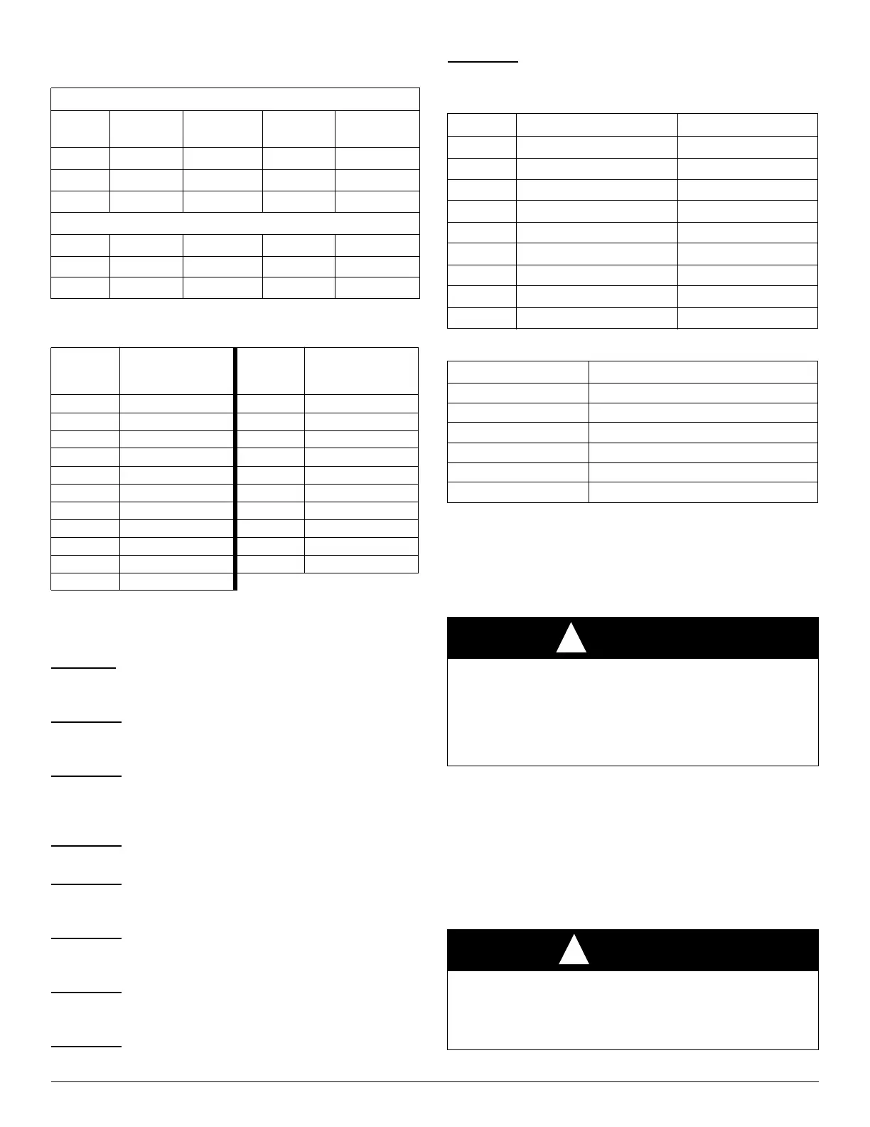
Table 14 – Required Operational Checks to Ensure Proper
Dissipation System Function
Normal Operation
Test # T-Stat Call Compressor Indoor Fan
Electric/Gas
Heat
1 None Off Off Off
2 Cool On On Off
3 Heat Off On On
Dissipation Activated
4 None Off On Off
5 Cool Off On Off
6 Heat Off On Off
Table 15 – Required Minimum Dissipation Mode Airflows,
based on Total System Refrigerant Charge Quantity
Total
System
Charge (lb)
Minimum Required
Dissipation Airflow
(CFM)
Total
System
Charge (lb)
Minimum Required
Dissipation Airflow
(CFM)
5 133 16 426
6 160 17 452
7 186 18 479
8 213 19 505
9 239 20 532
10 266 21 559
11 293 22 585
12 319 23 612
13 346 24 639
14 372 25 665
15 399
Table 16 – Flash Code Chart
Yellow LED Reason Mode
Solid Normal Operation Normal Operation
Flashing 1 Sensor >= 20% LFL Dissipation
Flashing 2 Sensor Open Dissipation
Flashing 3 Normal Mitigation after Leak Dissipation
Flashing 4 No Power to G Output Dissipation with no Blower
Flashing 5 Fault with A2L Digital Sensor Dissipation
Flashing 6 Test Button Stuck (>30 s) Dissipation
Flashing 7 Y or W Wiring Inverted Normal Operation
Flashing 8 Y or W Shorted Normal Operation
Table 17 – Wall-Hung FMA5 Control Board Test Functions
LED Status Description
Steady ON Normal Operation
OFF Power Supply Failure
Steady Flashing Dissipation Mode Active
3 Flash / Cycle A2L Sensor Error
4 Flash / Cycle A2L Sensor Communication Error
8 Flash / Cycle A2L Sensor Over Service Life
WARNING
!
ELECTRICAL SHOCK HAZARD
Failure to follow this warning could result in personal injury or death.
Disconnect all power to the unit before servicing the field wires or
removing the control package. The disconnect (when used) on the
access panel does not disconnect power to the line side of the
disconnect, but does allow safe service to all other parts of the unit.
CAUTION
!
CUT HAZARD
Failure to follow this caution may result in personal injury.
Sheet metal parts may have sharp edges or burrs. Use care and wear
appropriate protective clothing and gloves when handling parts.