FB, FE, FF1E, FFM, FG, FH, FJ, FMA, FT, FV, FX, FY, FZ, F54, PF: Service and Maintenance Instructions
Manufacturer reserves the right to change, at any time, specifications and designs without notice and without obligations.
13
low-voltage control of a humidifier through a standard humidistat. These
terminals are energized with 24VAC when G thermostat signal is
present. Alternately, the 24VAC signal may be sourced from the W and
C terminal block connections when electric heaters are used as primary
heating source. When using a Thermidistat™ Control, Zone Perfect
Plus, or Comfort Zone II, the 24VAC signal may be source directly from
the Thermidistat HUM terminal.
Dehumidify Mode
NOTE: Humidistat must open on humidity rise.
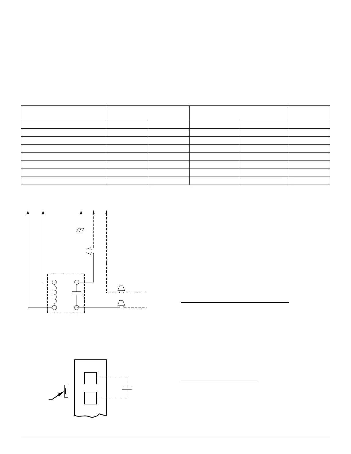
Latent capacities for systems using the FK4, FT4, FV4, and 40FK fan
coils are better than average systems. If increased latent capacity is an
application requirement, the field wiring terminal block provides
connection terminals for use of a standard humidistat. The FK4, FT4,
FV4, and 40FK fan coils will detect the humidistat contacts opening on
increasing humidity and reduce its airflow to approximately 80 percent
of nominal cooling mode airflow. This reduction will increase the
system latent capacity until the humidity falls to a level which causes the
humidistat to close its contacts. When the contacts close, airflow will
return to 100 percent of the selected cooling airflow. To activate this
mode, remove jumper J1 and wire in a standard humidistat. Carefully
consult product airflow data for cooling and dehumidification modes.
A98625
Fig. 11 – KFAIR0201ACR Relay Kit Wiring Schematic
A95316
Fig. 12 – Humidistat Wiring for De-Humidify Mode
InteliSense™ Technology (FT4, FT5)
This unit is InteliSense capable when used with an InteliSense
thermostat. InteliSense allows for the collection of performance data in
the cloud. The unit comes with two interchangeable sensors: a Return
Air Temperature (RAT) sensor and a Supply Air Temperature (SAT)
sensor for installation in the field. Make sure the sensors are connected
to the appropriate terminals for proper temperature data collection when
used with the InteliSense board. See installation instructions for detailed
information on RAT/SAT placement and installation.
The InteliSense board uses the existing Easy Select layout for airflow
selection with additional circuitry to manage the InteliSense data
collection. Refer to the thermostat instructions for Easy Select operation
details.
NOTE: When installing and servicing electronic equipment use
appropriate safety PPE and avoid damaging system components by
utilizing electrostatic discharge protection.
Connected Portal and Service Tech App
The Carrier Connected portal and Service Tech App provide a
connection between the dealer/service tech and the homeowner's system.
They can provide information about the homeowner's account,
equipment configuration, operating performance and fault code history,
current equipment status, and allow you to view and update thermostat
settings. They can perform remote service diagnostics using real time
suction line temperature and pressure w/ superheat calculation, liquid
line temperature and pressure with subcooling calculation, outdoor air
temperature, supply and return air temperatures, and blower motor
RPMs. The dealer's unique contractor PIN can be located through either
of these applications.
Power On LED/Board States
The amber LED is illuminated solid when there is power to the product.
The green LED is illuminated solid when there is communication
between the board and the InteliSense-enabled thermostat.
Table 6 – FV4/FT4 Motor Control Test Values (With 16-pin connector at motor unplugged)
Terminals
Jumpered
Volt Meter on 16-pin Harness Plug
Volt Meter on 12-pin
Easy Select Board Plug
Voltage
+ – + –
R to W1 Pin 2 Pin 1 Pin 7 Pin 9 24VAC
R to W2 Pin 13 Pin 1 Pin 4 Pin 9 24VAC
R to Y1 Pin 6 Pin 1 Pin 3 Pin 9 (-)12VDC
R to Y/Y2 Pin 14 Pin 1 Pin 2 Pin 9 (-)12VDC
R to G (LO) Pin 15 Pin 1 Pin 3 Pin 9 0VAC
R to G (MED) Pin 6 Pin 1 Pin 3 Pin 9 (-)12VDC
R to G (HI) Pin 14 Pin 1 Pin 2 Pin 9 (-)12VDC
24 VAC RELAY
FAN COIL
230 VAC OR
115 VAC BRANCH CKT
AUX1
(C)
AUX2
(G)
GND HOT NEUT
GRN
BLK
WHT
NO
COM
BLK
BLK
RED
RED
WHT
TO EAC
EASY SELECT
BOARD TERMINAL
BLOCK
D
H
J1
R
HUMIDISTAT
REMOVE
JUMPER