FB, FE, FF1E, FFM, FG, FH, FJ, FMA, FT, FV, FX, FY, FZ, F54, PF: Service and Maintenance Instructions
Manufacturer reserves the right to change, at any time, specifications and designs without notice and without obligations.
19
4. Inspect electrical connections for tightness and controls for proper
operation each heating and cooling season. Service as necessary.
Filter Assembly
To clean or replace air filter, push plastic connectors toward center of
unit and remove filter access panel outward. Push filter up and back into
unit. Then slide filter out.
Clean filter by using cold water and mild detergent. Rinse and allow
filter to dry. No oiling or coating of filter is required.
New filters are available from your local distributor. Place filter in slot
with cross-mesh binding up or facing cooling coil and replace filter
access panel.
Cooling Coil, Drain Pan, and Condensate Drain
The cooling coil is easily cleaned when it is dry. Inspect the coil and
clean (if necessary) before each cooling season. To check or clean
cooling coil, remove coil access panel. If coil is coated with dirt or lint,
vacuum it with a soft brush attachment.
Be careful not to bend coil fins. If coil is coated with oil or grease, clean
it with a mild detergent and water solution. Rinse coil thoroughly with
clear water. Be careful not to splash water on insulation.
FFM and FMA
Fan Motor
The FFMANP (018,024,030,036), FMA4P and FMA5L motor is
three-speed PSC direct drive. High-speed lead is black, medium-speed
lead is red, low-speed lead is blue, and common lead is purple. The
FFMANP (019,025,031,037) and FMA4X/5Xmotor is a five speed
ECM direct drive. The cooling speed tap is selected by connecting the
green wire to the desired motor tap number indicated on the motor plug.
For the electric heat fan speed selection connect the white wire to the
desired motor tap number indicated on the motor plug. Be sure proper
blower speed has been selected.
The blower motor in this unit has blower-off delays. The blower-off
delay is 30–90 seconds and will keep the motor running after a heating
or cooling call ends.
The motor is turned on through two different routes. The first occurs
when thermostat calls for the fan in cooling, heat pump, or fan-only
mode. A 24VAC signal is sent to relay, causing relay to close its
normally open contacts, turning fan on.
The second occurs when there is a call for electric heat. A 24VAC signal
is sent to heater sequencer/relay, causing it to close, directing 230V
through the normally closed contact of fan relay, turning fan on. The fan
remains on until sequencer/relay/PCB opens.
FMA5 only—has a third way to start the fan motor. If the dissipation
system detects a refrigerant leak, G is energized and completes the
circuit to the indoor blower motor.
If motor does not run, test motor for an open winding or a winding
shorted to motor case. If either is present, replace motor.
Time Delay
FFMANP (019,025,031,037) and FMA4X/5X have time delay built into
the motor logic. FFMANP (018,024,030,036), FMA4P and FMA5L
units with date codes prior to 1715V have sequencers. FFMANP
(018,024,030,036), FMA4P and FMA5L units with date codes 1715V or
later have a time delay printed circuit board.
The Time Delay Printed Circuit Board (PCB) s a logic controlled time
delay activated by low-voltage control signal (G) from thermostat. The
PCB includes a normally open relay which closes to energize the blower
motor when the G terminal is energized. Then when the G terminal is
de-energized the relay energizing the blower motor remains closed for
90–100 seconds before opening.
NOTE: Aluminum coil models with PSC motor can be wired to
different OFF time delay. See installation instructions for wiring
diagram.
FMA5X units have time delay built into the motor logic. See the Motor
Speed Taps table in the installation instructions. FMA5L have the time
delay functionality integrated into the control board.
CAUTION
!
CUT HAZARD
Failure to follow this caution may result in personal injury.
Sheet metal parts may have sharp edges or burrs. Use care and wear
appropriate protective clothing and gloves when handling parts.
WARNING
!
ELECTRICAL OPERATION HAZARD
Failure to follow this warning could result in personal injury or death.
Before installation or servicing system, always turn off main power to
system. There may be more than one disconnect switch. Turn off
accessory heater power if applicable. Lock out and tag switch with a
suitable warning label.
Table 11 – Speed Tap and Off -Delay Time (FMA4)
Speed
Tap
Off-Delay
Time
18 24 30 36
Tap 1 30 - - - -
Tap 2 90 Default - Default -
Tap 3 30 - - - -
Tap 4 90 - Default - Default
Tap 5 30 - - - -
Table 12 – FMA5X ECM Motor Speed Taps Delay Off Time Setting
Tap 18 24 30 36
Tap 1
30 30 30 30
Tap 2
30 30
30/90
*
*. Default setting
Where two numbers are shown, left represents Minor series 1 and right
represents Minor series 2.
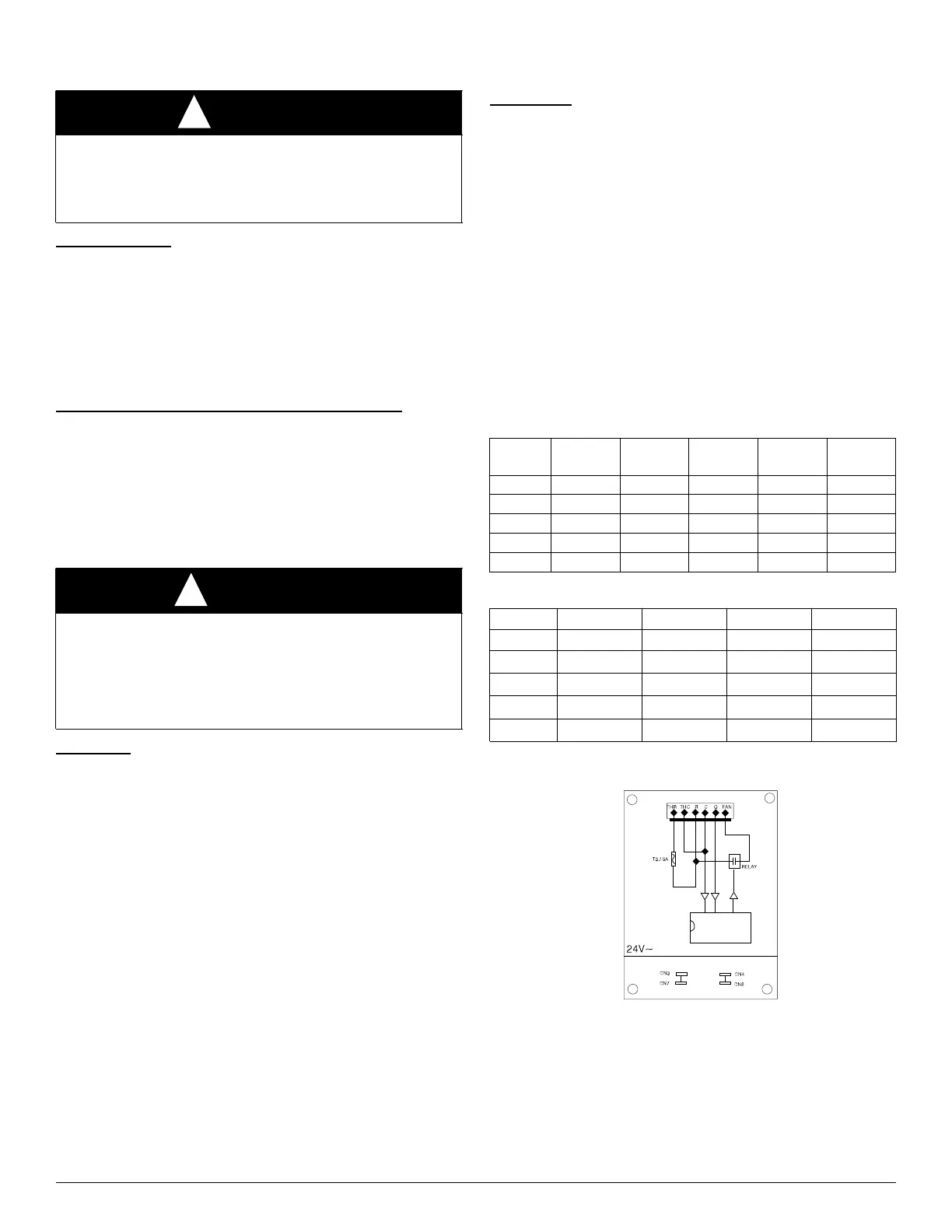
A150455B
Fig. 1 – Time Delay PCB Schematic
30/90
Tap 3
90
*
90 90/30 90/30
Tap 4
90/0 90/0 90
90
*
Tap 5
90
90
*
90/0 90/0
Comments:
1. The THR and THC are connected to transformer output.
2. When the G has signal, the FAN will supply 24VAC power
to control fan relay.
3. Whe the G signal is gone, the FAN will stop 24 VAC output
after 90 seconds.
4. CN3, CN7 are dummy connection terminals.