FB, FE, FF1E, FFM, FG, FH, FJ, FMA, FT, FV, FX, FY, FZ, F54, PF: Service and Maintenance Instructions
Manufacturer reserves the right to change, at any time, specifications and designs without notice and without obligations.
20
NOTE: The following sequence of operation is based on units installed
with PSC motor and Time Delay Printed Circuit Board (PCB), and all
FMA5L units. For units with ECM motor, the off-delay is programmed
into the motor. Follow Table 11 below, ECM Motor Speed Taps & the
corresponding blower OFF delays for each speed tap. For FMA5X units,
see the Motor Speed Taps table in the Installation Instructions.
Continuous Fan
Thermostat closes R to G. G energizes and completes circuit to indoor
blower motor. When G is de-energized, there is a 90-second blower
off-delay.
Cooling Mode
Thermostat energizes R to G, R to Y, and R to O (heat pump only). G
energizes and completes indoor blower motor. Y energizes outdoor unit
(O is energized for heat pump). When cooling call is satisfied, G is
de-energized, there is a 90-second blower off-delay.
Heat Pump Heating Mode
Thermostat energizes R to G and R to Y. G energizes and completes
circuit to indoor blower motor. When heating call is satisfied, G is
de-energized, there is a 90-second blower off-delay.
Heat Pump Heating with Auxiliary Electric Heat
Thermostat energizes R to G, R to Y, and R to W1. G energizes and
completes circuit to indoor blower motor. W1 energizes electric heat
relay(s) which completes circuit to heater element(s). When W1 is
de-energized, electric heat relay(s) open, turning off heater elements.
When G is de-energized there is a 90-second blower off-delay.
Electric Heat or Emergency Heat Mode
Thermostat closes R to W1. W1 energizes electric heat relay(s) which
completes circuit to heater element(s). Blower motor is energized
through normally closed contacts on fan relay. When W1 is
de-energized, electric heat relay(s) opens, there is no blower off-delay.
(units with ECM motor will have a blower off-delay based on motor
speed tap selection).
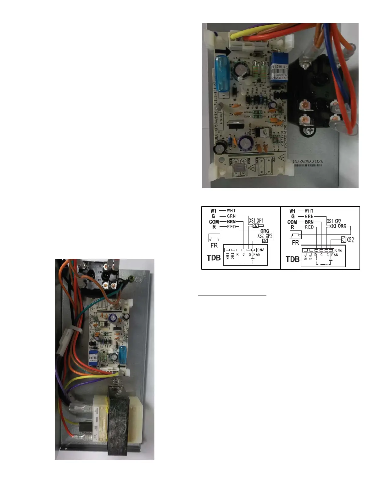
A150462
Fig. 16 – FMA4 Size 18 & 24 PCB
A150463
Fig. 17 – SMA4 Size 30 & 36 PCB
A180074
Fig. 18 – Time Delay Schematic
Electric Heater Service
Service can be completed with heater in place. Shut off power before
servicing.
Limit Switch
Refer to (Electric Heater Function and Troubleshooting on p24).
Sequencer
Early EHK2 heater kits included sequencers instead of relays. Refer to
(Electric Heater Function and Troubleshooting on p24).
Transformer
A 40VA transformer supplies 24V power for control circuit. Check for
208/230V on primary side of transformer. If present, check for 24V on
secondary side.
NOTE: Transformer is fused. Do not short circuit.
Fan Relay
Later EHK2 heater kits included relays instead of sequencers. Relay coil
is 24V. Check for proper control voltage. Replace relay if faulty.
Cleaning or Replacing Refrigerant Flow-Control Device
FFM, FMA4P
The piston can be removed and cleaned if believed to be plugged. This
unit’s piston is unique and replacements are available from RCD.
The filter drier should be located on the liquid line at the indoor unit to
prevent particulate from plugging the piston.