FB, FE, FF1E, FFM, FG, FH, FJ, FMA, FT, FV, FX, FY, FZ, F54, PF: Service and Maintenance Instructions
Manufacturer reserves the right to change, at any time, specifications and designs without notice and without obligations.
31
Before installation of replacement coil, verify the piston is the correct
orifice size. The correct size should be on the outdoor unit rating plate. If
in doubt, reuse the piston from the old indoor coil.
Use two wrenches to separate the 13/16" Chatleff nut from the
distributor body. The threads will contain Loctite anti-seize, do not
remove this from the threads.
Install the piston and reattach nut to finger tight plus 1/2 turn.
The distributor used on the all-aluminum replacement coil is also made
of aluminum. The distributor threads are coated with Loctite Heavy
Duty Anti-Seize which is a graphite/calcium fluoride formulation, for
applications that are free from copper, lead and sulfur. This product is
typically used in applications with an operating range of -20° F to
+2400° F (Fig. 29). When replacing a TXV it is recommended to reapply
with the same thread sealer. Extra care should be taken during brazing of
copper equalizer on the aluminum coils to prevent the braze material
from splattering on the aluminum. Also, route the copper equalizer so
that it doesn’t touch the aluminum components.
A14398
Fig. 29 – TXV Thread (Sealer) Location
Old Copper or Tin-Plated Coils with TXV
The all-aluminum replacement coil with piston will also be used for
TXV style coils by reusing the original TXV. An adapter is provided to
connect the replacement coil distributor to the original TXV (Fig. 30).
Insulation is also provided to wrap the copper adapter tube and brass
nuts to prevent any copper or brass particles from coming in contact with
the aluminum coil. Even if the adapter tube is not in contact with the
aluminum coil dripping condensation from the adapter tube can be a
mechanism of particulate transport.
A14397
Fig. 30 – Replacement Coil Distributor Adapter
If it is preferred to install the old TXV external to the cabinet due to
access, follow the steps below:
1. Field fabricate a piece of 3/8" OD copper tubing with flare and nut
to attach to the TXV outlet.
2. The piston in the replacement coil must be removed. Use two
wrenches to separate the 13/16" Chatleff nut from the distributor
body. The threads will contain Loctite anti-seize, do not remove this
from the threads.
3. Remove the piston
4. Reattach the inlet tube and tighten the nut finger tight plus 1/2 turn.
5. Remove the old coil and install replacement coil per instructions
below. Reinstall the fitting door to the cabinet.
6. Field fabricate a 3/8" OD copper tubing with flare and nut.
7. Braze this tubing and nut onto the liquid stub out.
8. Attach flare and nut to TXV outlet by tightening to finger tight plus
1/2 turn with two wrenches.
9. Drill equalizer hole into suction line and braze the equalizer into the
hole.
10. Attach the TXV bulb onto the suction line and insulate.
11. Insulate the entire TXV body and outlet tubing to prevent sweating.
Old All-Aluminum Coils with TXV
When replacing a previous all-aluminum coil that contains a TXV, the
old TXV can be reused and mounted inside the cabinet.
1. After removal of the distributor inlet tube and piston, the old TXV
is attached to the distributor with 13/16" Chatleff nut. The threads
contain Loctite anti-seize that can be reused.
2. Tighten the nut finger tight plus 1/2 turn.
3. The vapor header contains a small diameter stub tube for the
equalizer line.
4. Cut the end of the stub tube.
5. Insert TXV equalizer and braze together. Caution must be taken to
avoid braze splatter from the aluminum surfaces of the new coil.
Caution must be taken to avoid heating the factory joint of the stub
tube to the vapor header.
6. The vapor header contains an indentation for the TXV bulb. Attach
the bulb and insulate.
Installation – A-Coil Units Only
1. Recover system refrigerant.
a. Attach gage/manifold set to service valves.
b. Start unit in cooling mode.
c. Front seat (close) liquid line service valve.
d. Operate unit until vapor pressure reaches 5 psig (35kPa), or until
suction line LPS opens.
e. Turn off electrical supply to outdoor unit.
f. Front seat (close) vapor service valve.
g. Recover any remaining refrigerant.
A13359
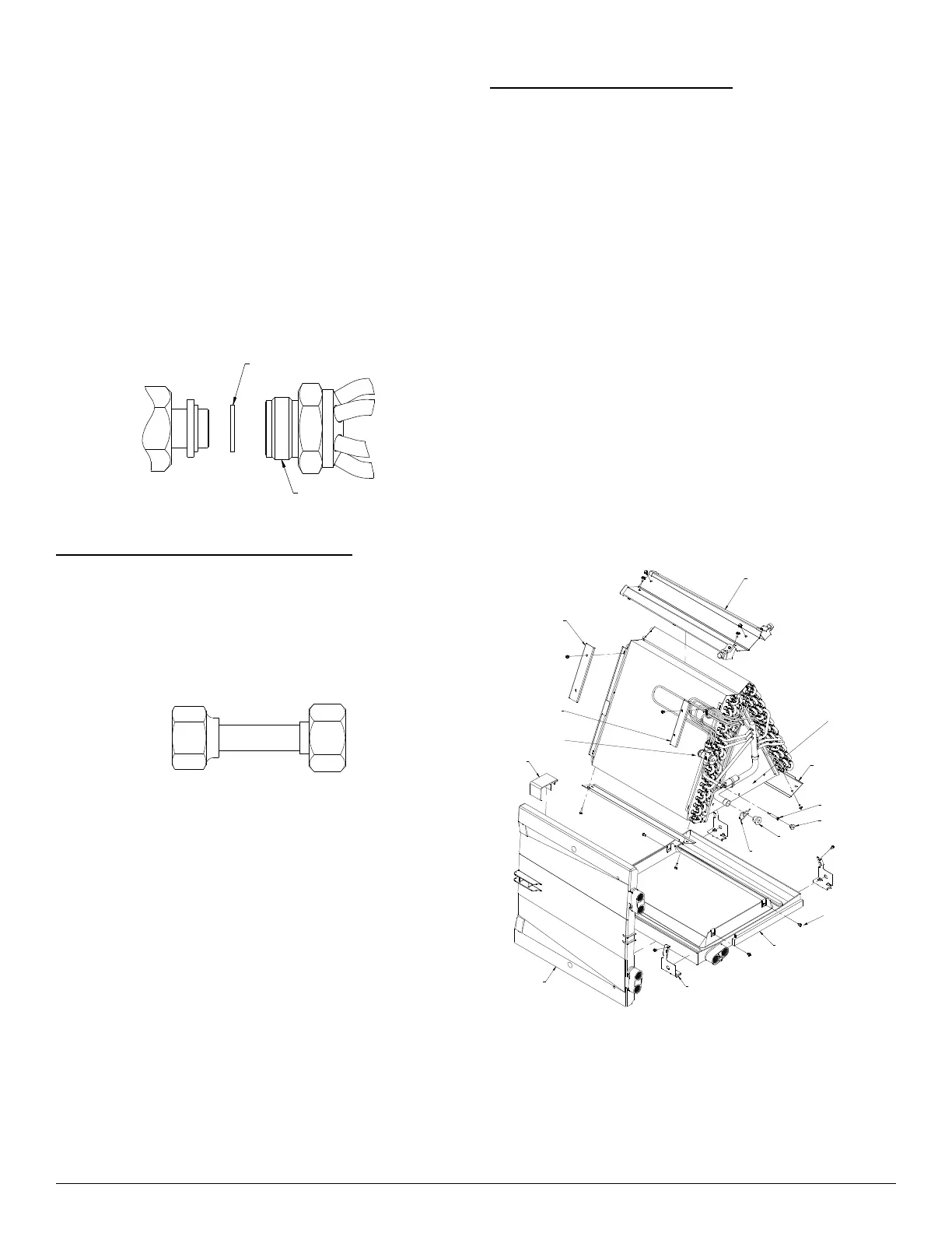
Fig. 31 – A-Coil Component Location
NOTE: All condenser coils hold only a factory-supplied amount of
refrigerant. Excess refrigerant, such as in long-line applications, may
cause compressor internal pressure relief valve to open (indicated by
sudden rise in vapor pressure) before refrigerant is recovered. If this
occurs, turn off electrical supply to outdoor unit immediately, front seat
(close) vapor service valve, and recover any remaining refrigerant.
2. Turn off electrical supply to indoor unit.
Cond. Trough
Coil Top Seal
Pan Shield
(2 per unit)
Coil Bracket
(4 per unit)
Vertical Condensate Pan
Horizontal
Condensate Pan
Strainer
Rubber Plug
Rubber Plug
Support
Cond. Trough
Drip Ring
TXV
Delta Plate
Screws-
Delta Plate To Pan
(4 per unit)