FB, FE, FF1E, FFM, FG, FH, FJ, FMA, FT, FV, FX, FY, FZ, F54, PF: Service and Maintenance Instructions
Manufacturer reserves the right to change, at any time, specifications and designs without notice and without obligations.
6
A13028
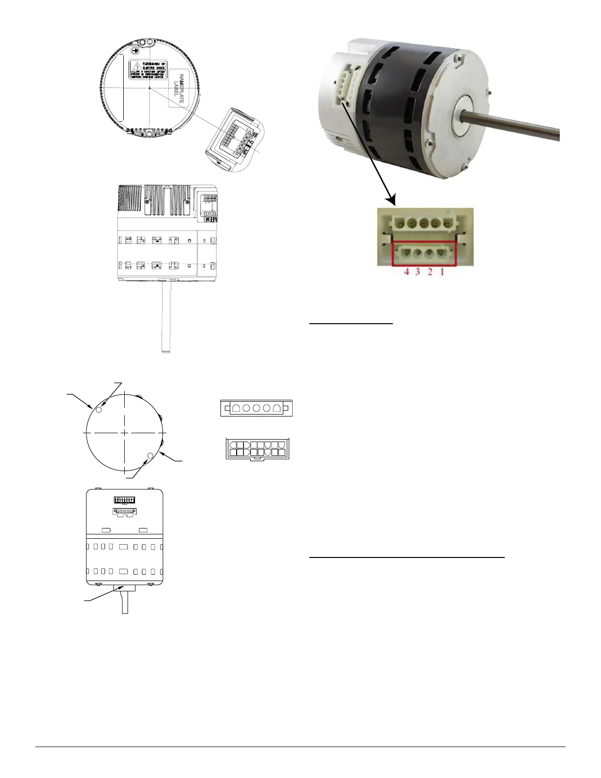
Fig. 5 – FV4 Motor / ECM5.0 Motor (pre-2023)
A98201
Fig. 6 – FV4 Motor / ECM2.3 Motor (pre-2023)
A230463
Fig. 7 – ECM Motor, post-2023
FV, FT4, FG4
Constant Air Flow
Unlike fan coils using induction motors where static pressure affects
airflow, these fan coils are constant airflow units. The blower delivers
requested airflow regardless of static pressure. Consult fan coil Product
Data for static pressure limits. The ECM2.3/5.0 is pre-programmed and
contains airflow tables for all modes of operation. Blower characteristics
(requested airflow, torque, and speed) are known from laboratory testing
If any two characteristics are known, the third is defined.
Requested airflow is known from Easy Select board configuration and
thermostat signals. Torque is known because it is directly related to
stator current, which is measured by motor control. Speed is measured
by counting back EMF pulses from stator windings. This information is
entered into an expression that calculates torque from speed and airflow
numbers. If calculation does not match stored blower characteristics,
torque is adjusted until agreement is reached. This calculation and
adjustment is performed every 0.8 seconds while motor is in operation.
There is no direct measure of static pressure, but unit does react to a
change in static to maintain constant airflow. A change in pressure will
result in a change in stator speed and torque. The motor will begin to
adjust on the next sampling, calculate new desired speed and torque, and
adjust as necessary.
Integrated Controls and Motor ECM2.3/5.0
An ECM2.3/5.0 is fed high voltage AC power through the 5-pin
connector (Fig. 6 or Fig. 5). The AC power is then internally rectified to
DC by a diode module. After rectification, DC signal is electronically
communicated and fed in sequential order to three stator windings. The
frequency of these commutation pulses determines motor speed. The
rotor is permanently magnetized.
An ECM2.3/5.0 is powered with high voltage at all times. The motor
will not run with high voltage alone. Low voltage must be applied to
control plug to run motor.
ECM2.3/5.0 Control Power
The ECM2.3/5.0 control power is supplied from R circuit through
printed circuit runs to motor control Connector-Pin 8, through motor
control harness to motor. The C side of low-voltage control power circuit
is connected by printed circuit runs to motor Connector pins 9, 10, and
11, then through motor control harness to motor.
12345
9
12345678
10 11 12 13 14 15 16
POWER CONNECTOR
CONTROL CONNECTOR
OPTIONAL SAFETY GROUND
DRAIN HOLE
DRAIN HOLE
OPTIONAL SAFETY GROUND
ENDSHIELD
DRAIN HOLE
CONTROL
POWER