FB, FE, FF1E, FFM, FG, FH, FJ, FMA, FT, FV, FX, FY, FZ, F54, PF: Service and Maintenance Instructions
Manufacturer reserves the right to change, at any time, specifications and designs without notice and without obligations.
7
Low-Voltage Circuit Fusing and Reference
The low-voltage circuit is fused by a board-mounted 5A
automotive-type fuse placed in series with transformer SEC2 and R
circuit. The C circuit of transformer is referenced to chassis ground
through a printed circuit run at SEC1 connected to metal standoff
marked.
For FT: The low-voltage circuit is fused by a board-mounted 5A
automotive fuse placed in series with the transformer SEC1 (24VAC)
and the R circuit. The C circuit of the transformer is referenced to
chassis ground through a printed circuit run at SEC2 (COM) connected
to metal standoff marked with ground symbol.
NOTE: The PCB must be mounted with two screws and motor ground
lead secured to blower housing or erratic motor operation can result.
Transformer, Motor, and Electric Heater Power Connection
Transformer high voltage supplied from electric heater package or high
voltage leads through 12-pin heater connector plug/recp2. The
ECM2.3/5.0 power connections are made at the transformer primary
terminals. The transformer secondary connections are made at SEC1 and
SEC2 connectors.
PCB Layout and Description (FT4, FV4)
NOTE: Layout of actual PCB is depicted in Fig. 8.
The Easy Select Board is the interface between the ECM motor and
other system components. The board offers choices of electric heater
size, outdoor unit size and type, comfort or efficiency settings, on and off
delay profiles, and continuous fan speed. The installer should select the
correct size of components that are being installed in each installation. If
no selections are made, the factory default settings are for the largest
heater, largest outdoor unit, AC system type, nominal airflow adjust, and
0/90 time delay.
A 16x4 motor signal translator is present for the translation of data from
the board to the motors and is mounted on the back of the PCB bracket.
NOTE: Outdoor unit model should have an AHRI rating with the
variable speed fan coil. Some outdoor unit models will not work
properly with this fan coil.
• Power for system is supplied from a 230VAC, 60-Hz line. Class 2
voltage (24VAC nom.), used for thermostat connections, is derived
from transformer located in close proximity to PCB.
– The 24VAC secondary circuit includes 5A automotive type fuse.
• Connection to heater panel is made through 12-pin connector PL-1.
Connections to thermostat are made at screw terminals. Twenty-one
pin terminals comprise field select taps for motor.
• Fuse Data: 5A automotive-type ATC/ATO (tan)
• 32V
• 200 percent current opening time of five seconds maximum
Electrical Connections
Twenty-one 0.110-in pin terminals are used to provide programming
selections for operating modes of ECM2.3/5.0. The selection modes are
listed below. For additional information, refer to Easy Select
Configuration Taps section.
• AUX Heat Range—(Violet Wire)
• AC/HP Size—(Blue Wire) Type—(Orange Wire)
• AC/HP CFM Adjust—(Black Wire)
• AC/HP Time Delay—(Grey Wire)
• Continuous Fan—(Yellow Wire)
Sequence of Operation (FT4, FV4)
Continuous Fan Mode
The thermostat closes circuit R to G. The unit delivers the airflow
selected for fan only operation.
Cooling Mode—Single Speed or Two-Speed High
Thermostat closes circuits R to G, R to Y/Y2 and R to O (heat pump
only). A circuit R to Y1 is required for two-speed high operation.
Airflow delivered the airflow selected by AC/HP SIZE selection and
CFM ADJUST selection.
Cooling Mode—Two-Speed Low
Thermostat closes R to G and R to Y1 and R to O (heat pump only). Unit
delivers two-speed low airflow for AC/HP SIZE and CFM ADJUST
selected.
Cooling + Dehumidify Mode (Thermidistat or Comfort Zone II-B and
Single-Speed Outdoor Unit Installed)
J1 jumper must be pulled from Easy Select Board. Control closes R to G,
R to Y/Y2, and R to O (heat pump only) and open R to DH.
Dehumidification is active when 24VAC is removed from DH terminal.
Unit delivers 20 percent less airflow.
SuperDehumidify Mode (Thermidistat or Comfort Zone II-B indoor
control, Single-Speed Outdoor Unit)
This mode is only activated by the indoor control when COOL to
DEHUMIDIFY and SUPERDEHUMIDIFY are configured at the
control and there is a call for dehumidfication without a call for cooling.
The control closes R to Y/Y2, R to O (heat pump only) and opens R to
DH and R to G. This signals the fan coil to run at minimum airflow for
maximum humidity removal. The control will cycle the equipment 10
minutes on and 10 minutes off until satisfied.
NOTE: Super Dehumidification and Thermidistat functionality is not
available with certain thermostat models. Verify with the thermostat
manufacturer if this functionality is critical to the application.
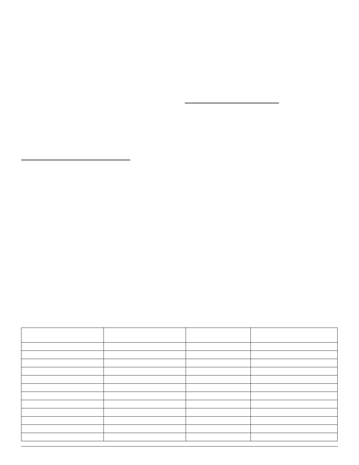
Table 1 – Motor and Modules
Model Size Motor Type Current Blower Motor P/N
Required Control Module
Replacement Kit Number
FV4B_002 ECM2.3 HD44AE131 RMOD44AE131
FV4B_003 ECM2.3 HD44AE132 RMOD44AE132
FV4B_005 ECM2.3 HD44AE133 RMOD44AE133
FV4B_006 ECM2.3 HD46AE244 RMOD46AE244
FV4C_002 (Series A) ECM2.3 HD44AR131 RMOD44AR131
FV4C_003 (Series A) ECM2.3 HD44AR132 RMOD44AR132
FV4C_005 (Series A) ECM2.3 HD44AR133 RMOD44AR133
FV4C_006 (Series A) ECM2.3 HD46AR244 RMOD46AR244
FV4C_002 (Series B) ECM5.0 HD44AR120 HK44ER120
FV4C_003 (Series B) ECM5.0 HD44AR121 HK44ER121
FV4C_005 (Series B) ECM5.0 HD44AR122 HK44ER122
FV4C_006 (Series B) ECM5.0 HD46AR223 HK46ER223