FB, FE, FF1E, FFM, FG, FH, FJ, FMA, FT, FV, FX, FY, FZ, F54, PF: Service and Maintenance Instructions
Manufacturer reserves the right to change, at any time, specifications and designs without notice and without obligations.
5
• The motor is communicated through 24VAC signals to
the 1, 2, 3, 4, 5 and C (common) terminals. Not all taps
are programmed, if low voltage is applied to an
non-programmed terminal, the motor will not operate,
which is normal. Verify the part number of the motor
matches the correct replacement motor part number for
the unit model number.
• Initiate a demand from the thermostat and check the
voltage between C (common) and terminal 1- 5. If
voltage is present and the motor isn’t operating, then the
motor/control module is failed.
(2.) Prior to installing the replacement control module, the
motor section condition needs to be verified.
• Check to see if the blower wheel spins freely.
• To check for short to ground, use an ohmmeter to
measure the resistance from any one of the motor
connector pins to the aluminum end plate of the motor.
This resistance should be greater than 100,000 ohms.
• Check the motor phase-to-phase resistance between each
of the leads in the three-pin motor connector. The
lead-to-lead resistance across any two leads should be
less than 20 ohms. Each lead-to-lead resistance should be
the same within ± 10 percent.
• If any motor fails any of the three tests, do not install a
new control module. The new control can fail if placed on
a defective motor.
The prior fan coil models with multi-speed ECM blower motors used a
printed circuit board, similar to the PSC models. The current fan coils do
not use the printed circuit board and rely on the motor control
programming to provide the off-delay timing.
Another design aspect of the control board was to provide a resistor in
the “G” circuit in case a power stealing thermostat was used. This
resistor is no part of the wiring harness, as shown on wiring diagram.
The resistor is a 2W, 1500-ohm resistor.
If the resistor has failed open, a likely cause is due to the power stealing
thermostat. Connecting C (common) may resolve the issue. Having an
open resistor should not affect the operation of the motor.
Fan Speed Selection
The fan speed selection is done at the motor connector. Units with or
without electric heaters require a minimum CFM. Refer to the unit
wiring label to ensure that the fan speed selected is not lower than the
minimum fan speed indicated.
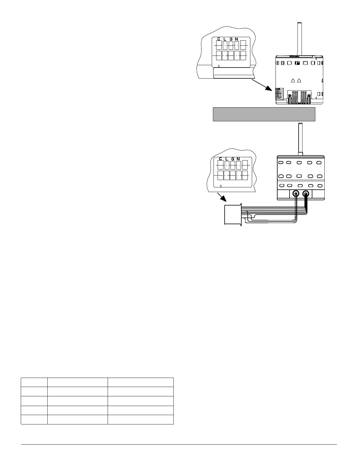
To change motor speeds disconnect the BLUE fan lead from motor
connector terminal No. 2 (factory default position) and move to desired
speed-tap; 1, 2, 3, or 5.
Speed-taps 1, 2, and 3 have a 90-second blower off time delay
pre-programmed into the motor. Speed-tap 4 is used for electric heat
only (with 0 second blower time delay) and the WHITE wire should
remain on tap 4. Speed-tap 5 is used for high static applications, but has
a 0-second blower time delay pre-programmed into the motor. See
Airflow Performance tables for actual CFM. Also, see Fig. 4 for motor
speed selection location.
NOTE: In low static applications, lower motor speed tap should be used
to reduce possibility of water being blown off coil.
† electric heat airflow is same CFM as Tap 3, except 0 sec off delay
‡ high static applications, see airflow tables for max airflow
A11048
Fig. 4 – Motor Speed Selection for FB4C, FJ4, FX4D, FZ4A, F54 &
PF4 (odd sizes)
Tap 1 Low 90 sec off delay
Tap 2 Medium 90 sec off delay
Tap 3 High 90 sec off delay
Tap 4 Electric heat † 0 sec off delay
Tap 5 Max ‡ 0 sec off delay
1 2 3 4 5
Speed Taps may be located on motor,
or on plug close to motor.
CLGN
1 2 3 4 5