FB, FE, FF1E, FFM, FG, FH, FJ, FMA, FT, FV, FX, FY, FZ, F54, PF: Service and Maintenance Instructions
Manufacturer reserves the right to change, at any time, specifications and designs without notice and without obligations.
18
ADVANCED TROUBLESHOOTING:
A13030
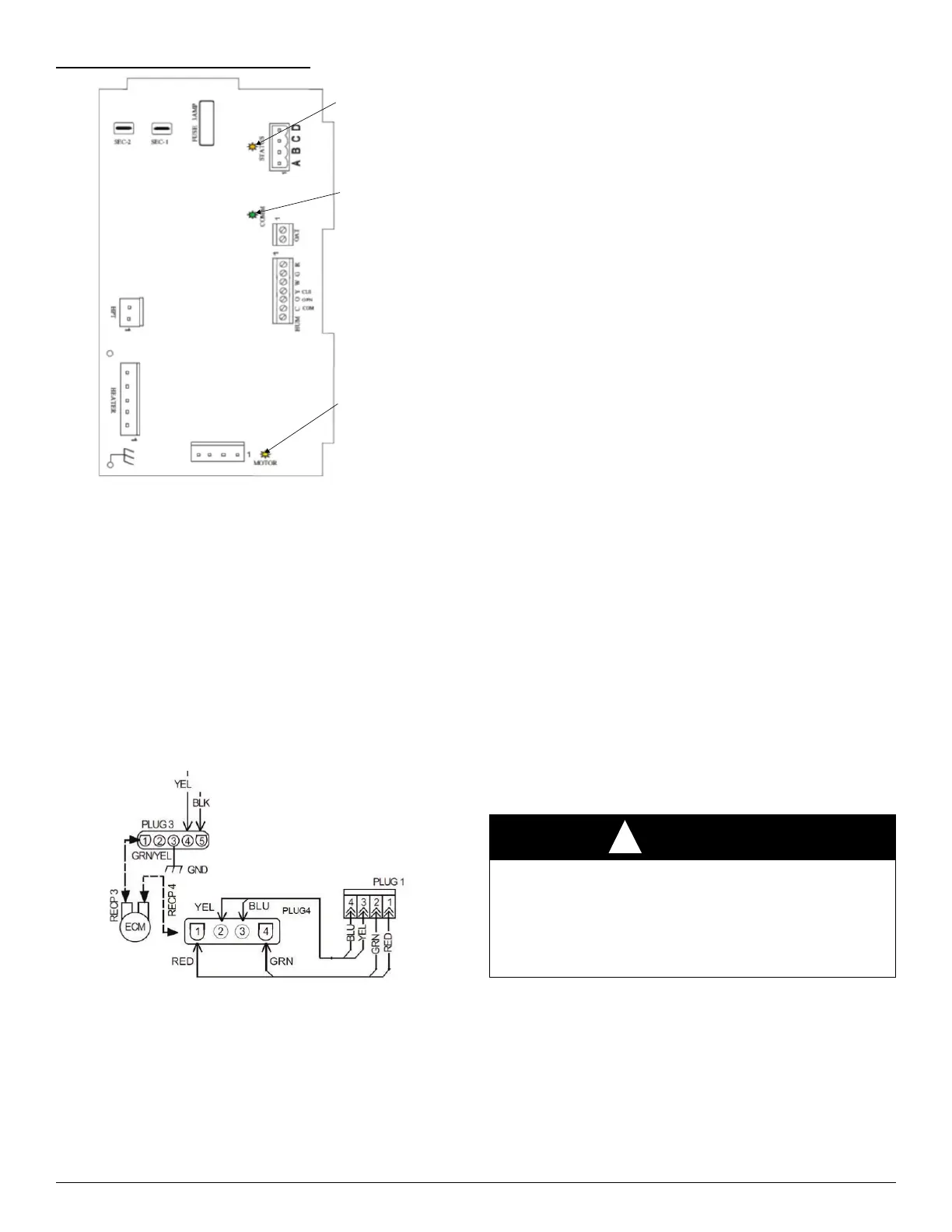
Fig. 14 – Circuit Board LED Locations
Troubleshooting the FE4/FE5 Fan Coil Circuit Board:
– Production Unit circuit board Fan Coil part number HK38EA061
– RCD Replacement circuit board HK38EA061
– Older circuit board part numbers HK38EA006, HK38EA009, and
HK38EA011
Primary test that should be performed:
Motor Line Voltage Check
1. Turn off power (240V).
2. Remove Plug 3 from ECM motor
3. Turn on power.
4. Check Plug 3, terminals 4 and 5, to ensure there are 240V.
5. Turn off power.
6. Reconnect Plug 3 to motor.
A13031
Fig. 15 – ECM / Plug Wiring Diagram
The following troubleshooting techniques will assist in determining the
correct component to replace when the Fan Coil Board presents a Fault
Code 44 or 41:
1. Disconnect power from the unit (240V).
2. Disconnect the ABCD connector from the board.
3. Disconnect Plug 1 from the board (Fig. 15).
4. Turn on power (240V).
5. After reestablishing power, you should receive Fault Code 44, and
the motor LED should be off.
6. Place a jumper across the R and G terminals on the low voltage
terminal block
7. Fault Code 44 should still be flashing.
8. The Motor LED should be flashing, indicating the board is able to
transmit a signal to the motor.
9. If Motor LED is not flashing, check to ensure that 24V is present
across R and C on the low voltage terminal block and that there is a
good connection with the R and G jumper.
10. If 24V is present and the jumper/connections are good,
11. Replace the board.
Check Board
1. If Fault Code 44 and the Motor LED are both flashing, place a DC
voltmeter across terminals PL1-1 Red (+) to PL1-2 Green (-)
(Fig. 15).
2. Across terminal PL1-1 and PL1-2, a 12VDC should be present. If
12VDC is not present, replace circuit board.
3. If Fault Code 44 is flashing and the Motor LED is flashing, place a
DC voltmeter across terminal PL1-3 (+) and PL1-2 (-).
4. Across terminal PL1-3 (+) and PL1-2 (-), the DC volt meter should
display 5VDC. The voltage should be very stable and should not
fluctuate more than 0.02VDC. If the voltage fluctuates, get a
different voltmeter before proceeding to the following steps.
5. Reconnect Plug 1 to circuit board and connect DC voltmeter across
terminals PL1-3 Yellow (+) and PL1-2 Green (-). Does the voltage
appear to fluctuate more than in step 15? Typical voltmeters will
show a fluctuation of 0.2VDC to 1VDC. The amount of fluctuation
is not important. You could see even more fluctuation depending on
the voltmeter used.
6. Check the blower motor serial output signal. The blinking LED on
the control board represents the serial output signal. You can
measure the signal with a DC voltmeter by removing Plug 1 from
the circuit board and connecting the DC voltmeter across PL1-4 (+)
and PL1-2 (-). The voltage should be near 0VDC but it will
fluctuate briefly several times per second. If you have an analog
voltmeter, the needle briefly will go high several times per second.
If you have a digital voltmeter with a bar graph, it will show a large
change in magnitude on the bar graph several times per second. If
you have a plain, digital voltmeter, it will show a brief fluctuation
in voltage, and the magnitude may vary depending on the voltmeter
used.
The minimum maintenance requirements for this equipment are as
follows:
1. Inspect and clean or replace air filter each month or as required.
2. Inspect cooling coil, drain pan, and condensate drain each cooling
season for cleanliness. Clean as necessary. An inspection port is
provided on all A-coil delta plates. Remove plastic plug to inspect.
Replace plug after inspection.
3. Inspect blower motor and wheel for cleanliness each heating and
cooling season. Clean as necessary.
Status
LED
Communication
LED
Motor
LED
WARNING
!
ELECTRICAL SHOCK HAZARD
Failure to follow this warning could result in personal injury or death.
Disconnect all power to the unit before servicing the field wires or
removing the control package. The disconnect (when used) on the
access panel does not disconnect power to the line side of the
disconnect, but does allow safe service to all other parts of the unit.