48
V
*Refer to Motor name plate.
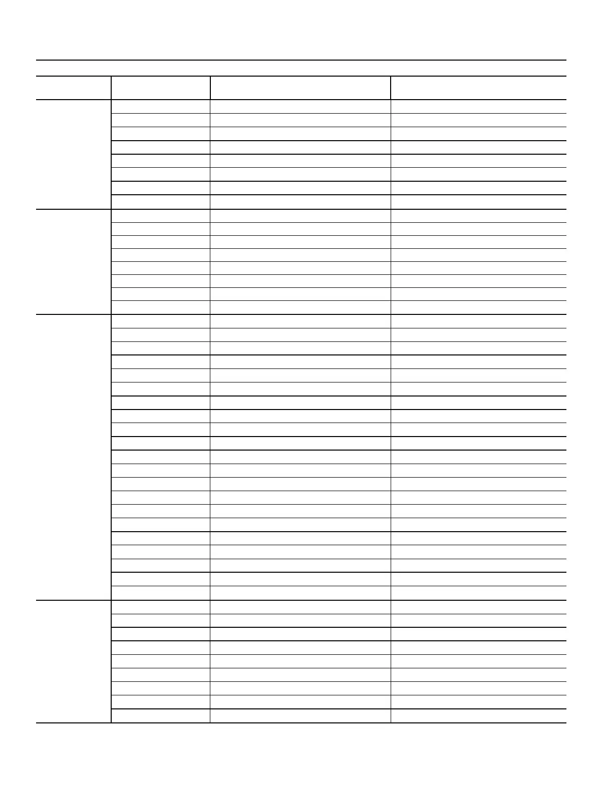
Table 25 — FD Factory Default Settings (cont)
DRIVE FACTORY CONFIGURATION VFD 2
GROUP NUMBER PARAMETER NUMBER DESCRIPTION VALUE
30
3006 Motor Thermal Time 1050s
3007 Motor Load Curve 100%
3008 Zero Speed Load 70%
3009 Break Point Frequency 35Hz
3010 Stall Function NOT SEL
3011 Stall Frequency 20 Hz
3012 Stall Time 20 Sec
3017 Earth Fault Enaled
31
3101 Number of Retries 5
3102 Trial Time 30Sec
3103 Delay Time 6 Sec
3104 AR Overcurrent Enabled
3105 AR Overvoltage Enabled
3106 AR Under voltage Enabled
3107 AR AI<Minimum Disabled
3108 AR External Fault (0) Disabled
34
3401 Signal Parameter 1 Output Freq
3402 Signal 1 Minimum 0
3403 Signal 1 Maximum 60 / 50 (Maximum motor operating Hertz)
3404 Output 1 DPS Form 0
3405 Output 1 DSP Unit % SP
3406 Output 1 Minimum 0
3407 Output 1 Maximum 100
3408 Signal Parameter 2 Current (Motor Current Measured by the Drive)
3409 Signal 2 Minimum 0
3410 Signal 2 Maximum FLA + 15% A
3411 Output 2 DPS Form 0
3412 Output DSP Unit A (2)
3413 Output 2 Minimum 0
3414 Output 2 Maximum FLA + 15% A
3415 Signal Parameter 3 AI-1
3416 Signal 3 Minimum 0
3417 Signal 3 Maximum 20mA
3418 Output 3 DPS Form 0
3419 Output DSP Unit mA(2)
3420 Output 3 Minimum 0
3421 Output 3 Maximum 20
40
4001 Gain 2.5
4002 Integration Time 3Sec
4005 Error Value Inver NO
4006 Units %
4007 Display Format x.xxx
4010 Setpoint Select Internal
4012 Setpoint Minimum 0V
4013 Setpoint Maximum 10V
4027 PID1 Parameter Set SET1
 Loading...