EasyManua.ls Logo

Carrier Performance 50VT User Manual

Carrier Performance 50VT
30 pages
To Next Page IconTo Next Page
Page #1 background imageLoading...
Page #1 background image
1
50VT
Performancet Single---Packaged Heat Pump Units with PuronR
(R ---410A) Refrigerant
S i n g l e --- A n d T h r e e --- P h a s e
2 to 5 Nominal Tons (Sizes 024---060)
Product Data
A99001
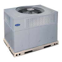
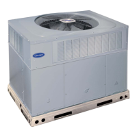
Fig. 1 -- Unit 50VT
Single-- Packaged Products with Energy--Saving Features and
PuronR refrigerant.
S Up to 14.5 SEER
S 8.0 HSPF
S 12 EER at 95_F(35_C) OD
S Factory--Installed TXV
S Multi--Speed Blower--Standard
FEATURES/BENEFITS
One--piece Heat Pump unit with optional electric heater, low
installation cost, dependable performance and easy maintenance.
Efficient operation High--efficiency design with SEERs
(Seasonal Energy Efficiency Ratio) of up to 14.5.
Puron Environmentally Sound Refrigerant is Carrier’s unique
refrigerant designed to help protect the environment. Puron is an
HFC refrigerant which does not contain chlorine that can harm the
ozone layer. Puron refrigerant is in service in millions of systems,
proving highly reliable, environmentally sound performance.
Easy Installation
Factory--assembled package is a compact, fully self--contained,
heat pump unit that is prewired, pre--piped, and pre--charged for
minimum installation expense. These units are available in a
variety of standard capacity ranges with voltage options to meet
residential and light commercial requirements. Units are
lightweight and install easily on a rooftop or at ground level. The
high tech composite base eliminates rust problems associated with
ground level applications.
Durable, dependable components Compressors are designed
for high efficiency. Each compressor is hermetically sealed against
contamination to help promote longer life and dependable
operation. Each compressor also has vibration isolation to provide
quieter operation. All compressors have internal high pressure and
overcurrent protection.
Direct --drive multi--speed brushless DC blower motor is
standard on all 50VT models. Direct--drive, PSC condenser-- fan
motors are designed to help reduce energy consumption and
provide for cooling operation down to 40_F(4.4_C) outdoor
temperature. MotormasterR II low ambient kit is available as a
field installed accessory.
Thermostat Controls designed to work as a system with Carrier’s
small packaged product.
Thermostatic Expansion Valve -- A hard shutoff, balance port
TXV maintains a constant superheat at the evaporator exit (cooling
cycle) resulting in higher overall system efficiency.
Refrigerant system is designed to provide dependability. Liquid
filter driers are used to promote clean, unrestricted operation. Each
unit leaves the factory with a full refrigerant charge. Refrigerant
service connections make checking operating pressures easier.
High and Low Pressure Switches provide added reliability for the
compressor.
Indoor and Outdoor coils are computer--designed for optimum
heat transfer and efficiency. The indoor coil is fabricated from
copper tube and aluminum fins and is located inside the unit for
protection against damage. The outdoor coil is internally mounted
on the top tier of the unit. Copper fin coils and pre-- coated fin coils
are available from the factory by special order. These coils are
recommended in applications where aluminum fins are likely to be
damaged due to corrosion. They are ideal for seacoast applications.
Low sound ratings ensure a quiet indoor and outdoor
environment with sound ratings as low as 72dBA.
Easy to service cabinets provide easy single--panel accessibility to
serviceable components during maintenance and installation. The
base with integrated drain pan provides easy ground level
installation with or without a mounting pad. Convenient
hand-- holds are provided to manipulate the unit on the jobsite. A
nesting feature ensures a positive basepan to roof curb seal when
the unit is roof mounted. A convenient 3/4--in. wide perimeter
flange makes frame mounting on a rooftop easy.
Convertible duct configuration
Unit is designed for easy use in either downflow or horizontal
applications. Each unit is easily converted from horizontal to
downflow with the two duct covers, standard on 3 phase units and
available as an accessory for single phase units. Downflow
operation is easily provided in the field to allow vertical ductwork
connections. The basepan utilizes knockout style seals on the
bottom openings to ensure a positive seal in the horizontal airflow
mode.
Cabinets are constructed of heavyduty, phosphated, zinc--coated
prepainted steel capable of withstanding 500 hours in salt spray.
Interior surfaces of the evaporator and electric heater compartments
are insulated with cleanable semi--rigid insulation board, which
Question and Answer IconNeed help?

Do you have a question about the Carrier Performance 50VT and is the answer not in the manual?

Carrier Performance 50VT Specifications

General IconGeneral
SEER2Up to 16.5
RefrigerantR-410A
Cooling Capacity (BTU/h)60, 000
Heating Capacity (BTU/h)60, 000
Voltage208/230

Summary

Product Data

FEATURES/BENEFITS

Highlights key features and benefits of the 50VT heat pump units, including efficiency and ease of installation.

Efficient operation

Details the high-efficiency design of the 50VT units, emphasizing SEER ratings.

Puron Refrigerant

Explains the environmental benefits and reliability of Puron refrigerant used in the units.

Easy Installation

Describes the unit's factory-assembled package and ease of installation.

MODEL NUMBER NOMENCLATURE

Type of Unit

Defines the unit type as a single packaged heat pump unit.

Nominal Cooling Capacity

Lists the nominal cooling capacities for different unit sizes in tons.

Electrical Supply

Specifies the available electrical supply options for the units.

Options

Lists various factory-installed options available for the units.

ARI CAPACITIES

COOLING CAPACITIES AND EFFICIENCIES

Presents cooling capacities, EER, and SEER ratings for different unit sizes.

HEAT PUMP HEATING CAPACITIES AND EFFICIENCIES

Details heating capacities, COP, and HSPF for various unit sizes.

PHYSICAL DATA - UNIT 50VT

UNIT SIZE

Details physical specifications for each unit size, including weight and dimensions.

COMPRESSOR QUANTITY

Indicates the number of compressors per unit.

REFRIGERANT

Specifies the type and quantity of refrigerant used in the units.

OUTDOOR COIL

Provides specifications for the outdoor coil, including rows, fins per inch, and face area.

INDOOR BLOWER

Details specifications for the indoor blower, including airflow and size.

A-WEIGHTED SOUND POWER LEVEL (dBA)

Presents sound level data in dBA for different unit sizes and frequencies.

OPTIONS AND ACCESSORIES

Factory-installed options

Lists factory-installed options like louver grilles and coil options.

Field-installed accessories

Details various accessories that can be installed in the field.

Economizer with Solid-State Controls and Barometric Relief Dampers

Explains the function of the economizer for free cooling and reduced compressor operation.

Electric Heaters

Describes electric heaters for additional heat, noting single-point power supply.

Filter Rack

Highlights features of the filter rack for easy installation and serviceability.

Flat Roof Curbs

Mentions available flat roof curb sizes for roof-mounted applications.

Square-to-Round Duct Transition Kit

Describes the kit to adapt units to round ductwork.

Corporate Thermostats

Details thermostat options for system heating and cooling control.

Crankcase heater

Explains the crankcase heater's role in preventing floodback.

Compressor Start Kit

Describes the start kit for single-phase units to aid compressor start-up.

Rigging Kit

Details the rigging kit for lifting units during rooftop applications.

Low Ambient Kit (Motormaster® II Control)

Explains the low ambient kit for operation at low outdoor temperatures.

ELECTRIC HEATERS

ORDERING NO.

Lists ordering numbers for electric heater modules.

NOMINAL CAPACITY (kW @ 240 or 480 VOLTS)

Specifies the power capacity of electric heaters in kW.

USED WITH SIZES

Indicates which unit sizes are compatible with each electric heater.

Minimum Airflow for Reliable Electric Heater Operation (cfm)

Provides minimum airflow requirements for electric heater operation.

ECONOMIZER

SIDE VIEW

Diagram showing the side view of the economizer installation.

DETAIL

Provides a detailed view of the economizer base and flange.

FILTER RACK

TOP FILTER RACK

Illustrates the top filter rack component.

BOTTOM FILTER RACK

Illustrates the bottom filter rack component.

MANUAL OUTSIDE AIR DAMPER

MANUAL OUTSIDE AIR HOOD

Shows the hood for the manual outside air damper.

DAMPER BLADE

Diagrammatically represents the damper blade.

UNIT DIMENSIONS - 50VT024-030

TOP VIEW

Diagram showing the top view of the unit dimensions.

LEFT SIDE VIEW

Diagram showing the left side view of the unit dimensions.

FRONT VIEW

Diagram showing the front view of the unit dimensions.

RIGHT SIDE VIEW

Diagram showing the right side view of the unit dimensions.

REAR VIEW

Diagram showing the rear view of the unit dimensions.

REQUIRED CLEARANCES TO COMBUSTIBLE MATL.

Specifies required clearances for combustible materials.

REQUIRED CLEARANCE FOR OPERATION AND SERVICING

Details clearances needed for unit operation and servicing.

UNIT DIMENSIONS - 50VT036-060

TOP VIEW

Diagram showing the top view of the unit dimensions.

LEFT SIDE VIEW

Diagram showing the left side view of the unit dimensions.

FRONT VIEW

Diagram showing the front view of the unit dimensions.

RIGHT SIDE VIEW

Diagram showing the right side view of the unit dimensions.

REAR VIEW

Diagram showing the rear view of the unit dimensions.

REQUIRED CLEARANCES TO COMBUSTIBLE MATL.

Specifies required clearances for combustible materials.

REQUIRED CLEARANCE FOR OPERATION AND SERVICING

Details clearances needed for unit operation and servicing.

ACCESSORY DIMENSIONS

Roof Curb for Small Cabinet

Dimensions and installation notes for small cabinet roof curbs.

Roof Curb for Large Cabinet

Dimensions and installation notes for large cabinet roof curbs.

NOTES:

Provides important notes regarding roof curb installation and usage.

RIGGING WEIGHTS (SMALL CABINET)

Unit

Lists unit sizes for rigging weight calculation.

Shipping Weight

Provides shipping weights for small cabinet units.

Rigging Weight

Provides rigging weights for small cabinet units.

RIGGING WEIGHTS (LARGE CABINET)

Unit

Lists unit sizes for rigging weight calculation.

Shipping Weight

Provides shipping weights for large cabinet units.

Rigging Weight

Provides rigging weights for large cabinet units.

SELECTION PROCEDURE (WITH EXAMPLE)

1. Determine cooling and heating requirements at design conditions:

Step 1: Identify cooling and heating needs based on design conditions.

2. Select unit based on required cooling capacity.

Step 2: Choose the unit size matching the required cooling capacity.

3. Select heating capacity of unit to provide design condition requirement.

Step 3: Determine heating capacity and need for accessory electric heat.

4. Determine fan speed and power requirements at design conditions.

Step 4: Calculate fan speed and power needs based on design conditions.

5. Select unit that corresponds to power source available.

Step 5: Choose the unit based on available electrical power source.

PERFORMANCE DATA

024 Cooling Extended Performance Table

Provides detailed cooling performance data for the 024 unit size.

030 Cooling Extended Performance Table

Provides detailed cooling performance data for the 030 unit size.

PERFORMANCE DATA (CONT)

030 Cooling Extended Performance Table

Continued cooling performance data for the 030 unit size.

030 Heating Extended Performance Table -10-60 (-23.3-15.6°C)

Heating performance data for the 030 unit size across various temperatures.

PERFORMANCE DATA (CONT)

036 Cooling Extended Performance Table

Detailed cooling performance data for the 036 unit size.

036 Heating Extended Performance Table -10-60 (-23.3-15.6°C)

Heating performance data for the 036 unit size across various temperatures.

PERFORMANCE DATA (CONT)

042 Cooling Extended Performance Table

Detailed cooling performance data for the 042 unit size.

042 Heating Extended Performance Table -10-60 (-23.3-15.6°C)

Heating performance data for the 042 unit size across various temperatures.

PERFORMANCE DATA (CONT)

048 Cooling Extended Performance Table

Detailed cooling performance data for the 048 unit size.

048 Heating Extended Performance Table -10-60 (-23.3-15.6°C)

Heating performance data for the 048 unit size across various temperatures.

PERFORMANCE DATA (CONT)

060 Cooling Extended Performance Table

Detailed cooling performance data for the 060 unit size.

060 Heating Extended Performance Table -10-60 (-23.3-15.6°C)

Heating performance data for the 060 unit size across various temperatures.

LEGEND

COOLING NOTES:

Provides essential notes and formulas for interpreting cooling performance data.

PERFORMANCE DATA (CONT)

Wet Coil Air Delivery* - Horizontal and Downflow Discharge - Unit 50VT024-060

Air delivery data for wet coil conditions across various static pressures.

Economizer 1-in. Filter Pressure Drop (in. wc)

Provides pressure drop values for economizer filters.

Multiplication Factors

Lists multiplication factors for voltage and heater ratings.

Electric Heat Pressure Drop Table

Details pressure drop for electric heat in different cabinet sizes.

50VT Wet Coil Pressure Drop

Presents wet coil pressure drop data for various unit sizes and airflows.

Filter Pressure Drop Table (IN. W.C.)

Dry Coil Air Delivery* - Horizontal and Downflow Discharge - Unit 50VT024-060

Air delivery data for dry coil conditions across various static pressures.

TYPICAL PIPING AND WIRING

TOP COVER

Diagram illustrating the top cover of the unit.

RETURN AIR

Shows the return air path in the unit's typical layout.

INDOOR THERMOSTAT

Indicates the location of the indoor thermostat.

FROM POWER SOURCE

Shows the connection point for the main power source.

APPLICATION DATA

Condensate trap

Specifies the requirement for a field-supplied condensate trap.

Maximum cooling airflow

Details the maximum recommended cooling airflow per ton.

Minimum cooling airflow

Provides minimum cooling airflow recommendations and potential issues.

Minimum ambient cooling operation temperature

States minimum ambient temperatures for cooling operation and low ambient kit.

Maximum operating outdoor air temperature for cooling is 125°F (51.7°C).

Specifies the maximum operating outdoor air temperature for cooling.

Ductwork

Instructions for securing downflow and horizontal discharge ductwork.

To convert a unit to downflow discharge

Describes the process of converting the unit for downflow discharge.

BALANCE POINT WORKSHEET

BUILDING HEAT LOSS, UNIT INTEGRATED HEATING CAPACITY, MBTUH

Label for the Y-axis of the balance point worksheet.

OUTDOOR TEMPERATURE, °F

Label for the X-axis of the balance point worksheet.

BASED ON INDOOR ENT. AIR AT 70 °F AND AT RATED CFM

Indicates the basis for the data presented on the worksheet.

ELECTRICAL DATA

UNIT

Table listing unit model numbers.

NOMINAL V-PH-HZ

Specifies the nominal voltage, phase, and frequency for units.

COMPRESSOR

Details compressor electrical specifications like RLA, LRA, FLA.

ELECTRIC HEAT

Lists electrical data for electric heat options.

POWER SUPPLY

Provides power supply details including fuse/breaker and MCA/MOCP.

LEGEND

NOTES:

Provides important notes regarding electrical compliance and voltage imbalance.

EXAMPLE: Supply voltage is 230-3-60.

Illustrates voltage calculation for a 3-phase supply.

Determine maximum deviation from average voltage.

Instructions for finding voltage deviation.

Determine percent of voltage imbalance

Provides the formula for calculating voltage imbalance percentage.

TYPICAL WIRING SCHEMATIC - 208/230-1-60

CONNECTION WIRING DIAGRAM

Diagram showing the unit's connection wiring.

LADDER WIRING DIAGRAM

Schematic illustrating the electrical logic and component connections.

LEGEND

Defines symbols and abbreviations used in the wiring diagrams.

DIP SWITCH SETTINGS

Information on dip switch settings for unit configuration.

TYPICAL WIRING SCHEMATIC - 208/230-3-60

CONNECTION WIRING DIAGRAM

Diagram showing the unit's connection wiring for 3-phase.

LADDER WIRING DIAGRAM

Schematic illustrating the electrical logic for 3-phase units.

LEGEND

Defines symbols and abbreviations used in the wiring diagrams.

DIP SWITCH SETTINGS

Information on dip switch settings for unit configuration.

TYPICAL WIRING SCHEMATIC - 460-3-60

CONNECTION WIRING DIAGRAM

Diagram showing the unit's connection wiring for 460V 3-phase.

LADDER WIRING DIAGRAM

Schematic illustrating the electrical logic for 460V 3-phase units.

DIP SWITCH SETTINGS

Information on dip switch settings for unit configuration.

CONTROLS

Operating sequence

Describes the unit's sequence of operation for power, cooling, and heating.

Cooling

Explains the sequence of operations during cooling mode.

Heating

Explains the sequence of operations during heating mode.

Defrost

Details the defrost control board and operation, including Quiet Shift.

NOTE:

Provides notes on compressor time delay and defrost control board functionality.

GUIDE SPECIFICATIONS (CONT)

Packaged Heat Pumps

General guide specifications for packaged heat pumps.

HVAC Guide Specifications

Specific guide specifications for the HVAC system.

Part 1-General

General information covering system description and quality assurance.

SYSTEM DESCRIPTION

Overview of the air-to-air heat pump unit's design and features.

QUALITY ASSURANCE

Details quality standards and certifications the unit meets.

DELIVERY, STORAGE AND HANDLING

Guidance on proper delivery, storage, and handling of the unit.

Part 2 - Products

Specifications for individual product components.

EQUIPMENT

Details the main equipment components and their features.

A. General:

General description of the factory-assembled heat pump unit.

B. Unit Cabinet:

Specifications for the unit's cabinet construction and features.

C. Fans:

Details about the indoor and outdoor fan specifications.

D. Compressor:

Specifications for the compressor, including type and isolation.

E. Coils:

Details on the construction of indoor and outdoor coils.

F. Refrigerant Metering Device:

Specifies the type of refrigerant metering device used.

G. Filters:

Information on the type and size of filters used.

H. Controls and Safeties:

Details on unit controls, safeties, and low-voltage circuits.

I. Operating Characteristics:

Describes operational capabilities under various ambient conditions.

J. Electrical Requirements:

Specifies electrical connection requirements for the unit.

K. Motors:

Details on motor types, bearings, and overload protection.

L. Special Features Available:

Lists optional features that can be added to the unit.

GUIDE SPECIFICATIONS (CONT)

4. Flat Roof Curb:

Instructions for installing flat roof curbs, including seal strip and wood nailer.

5. Manual Outdoor Air Damper:

Details the manual outdoor air damper package for ventilation.

6. Thermostat:

Specifies thermostat functions for heating and cooling control.

7. Low Ambient Package:

Describes the low ambient package for outdoor fan control.

8. Filter Rack Kit:

Information on the filter rack kit for downflow applications.

9. Square-To-Round Duct Transitions (024-048):

Details the kit for converting duct openings from rectangular to round.

10. Crankcase Heater:

Explains the crankcase heater for low-load cooling protection.

11. Electric heaters:

Details on electric heaters as a field-installed option.
Related product manuals