PG96MSA: Installation, Start-up, Operating and Service and Maintenance Instructions
Manufacturer reserves the right to change, at any time, specifications and designs without notice and without obligations.
16
A230007
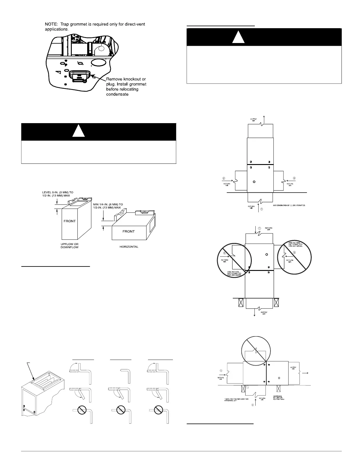
Fig. 18 – Horizontal Drain Trap Grommet
INSTALLATION
Upflow Installation
NOTE: The furnace must be pitched as shown in Fig. 19 for proper
condensate drainage.
A11237
Fig. 19 – Furnace Pitch Requirements
Supply Air Connections
For a furnace not equipped with a cooling coil, the outlet duct shall be
provided with a removable access panel. This opening shall be
accessible when the furnace is installed and shall be of such a size that
the heat exchanger can be viewed for possible openings using light
assistance or a probe can be inserted for sampling the air stream. The
cover attachment shall prevent leaks.
Connect supply-air duct to flanges on furnace supply-air outlet. Bend
flange upward to 90° with wide duct pliers. See Fig. 20. The supply-air
duct must be connected to ONLY the furnace supply-outlet-air duct
flanges or air conditioning coil casing (when used). DO NOT cut main
furnace casing side to attach supply air duct, humidifier, or other
accessories. All supply-side accessories MUST be connected to duct
external to furnace main casing.
A10493
Fig. 20 – Duct Flanges
Return Air Connections
The return-air duct must be connected to bottom, sides (left or right), or a
combination of bottom and side(s) of main furnace casing. Bypass
humidifier may be attached into unused return air side of the furnace
casing. See Fig. 21, Fig. 22, and Fig. 23.
A11036
Fig. 21 – Upflow Return Air Configurations and Restrictions
A11037
Fig. 22 – Downflow Return Air Configurations
and Restrictions
A11038
Fig. 23 – Horizontal Return Air Configurations and Restrictions
Bottom Return Air Inlet
These furnaces are shipped with bottom closure panel installed in bottom
return-air opening. Remove and discard this panel when bottom return
air is used. To remove bottom closure panel, see Fig. 24.
NOTICE
!
Cabinet air leakage is less than 2% at 1.0 in. w.c. Cabinet air leakage is
less than 1.4% at 0.5 in. w.c. when tested in accordance with ASHRAE
Standard 193.
UPFLOW DOWNFLOW HORIZONTAL
YES
NO
NO
YES
YES
YES
NO
120°
MIN
YES
120°
MIN
YES
120°
MIN
90°
90°
PERFORATED
DISCHARGE DUCT
FLANGE
WARNING
!
FIRE HAZARD
A failure to follow this warning could cause personal injury, death
and/or property damage.
Never connect return-air ducts to the back of the furnace. Follow
instructions below.
HORIZONTAL TOP
RETURN NOT
PERMITTED FOR
ANY MODEL