PG96MSA: Installation, Start-up, Operating and Service and Maintenance Instructions
Manufacturer reserves the right to change, at any time, specifications and designs without notice and without obligations.
28
A230219
A230220
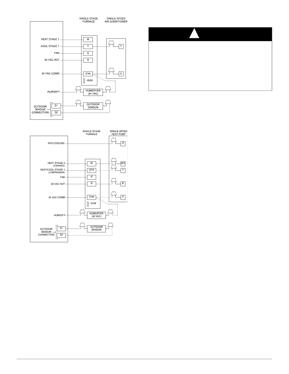
Fig. 38 – Thermostat Wiring Diagrams for Single Stage Furnace
with Single-Speed A/C & Heat Pump
Notes for thermostat wiring diagrams:
1. Thermostat output signals may vary. Consult thermostat installation
instructions for more information.
2. Refer to outdoor equipment Installation Instructions for additional
information and setup procedure.
3. Configure the thermostat for air conditioner installations. Refer to
thermostat instructions.
4. Configure thermostat for dual fuel operation. Refer to thermostat
instructions.
5. Heat pump MUST have a high-pressure switch for dual fuel
applications.
6. For Single-stage AC or HP, configure thermostat for single-stage
compressor operation. Refer to thermostat instructions.
7. NO connection should be made to the furnace HUM terminal when
utilizing the thermostat’s 24-volt humidifier output.
8. Thermostat terminal connection order on furnace control may vary-
reference furnace control labeling for designations
VENTING
NOTE: Planning for the venting system should be done in conjunction
with planning for the ductwork, drainage, and furnace accessories, such
as air cleaners and humidifiers. Begin assembling the venting system
AFTER the furnace is set in place in the required orientation.
Venting for this furnace shall follow all Local codes for Category IV
venting systems. This furnace is CSA approved for venting with
PVC/ABS DWV venting systems. This furnace is also CSA approved
for venting with M&G DuraVentRPolyProR or Centrotherm InnoflueR
polypropylene venting systems using single wall straight and flex, and
required fittings (elbows, reducers, increasers, connectors, adapters)
only.
NOTE: THESE INSTRUCTIONS DO NOT CONTAIN DETAILED
INSTALLATION INSTRUCTIONS FOR POLYPROPYLENE
VENTING SYSTEMS. Refer to the polypropylene venting system
manufacturer’s installation instructions for the polypropylene venting
system installation.
NOTE: When using polypropylene venting systems, all venting
materials used, including the vent terminations, must be from the same
manufacturer.
Special Venting Requirements for Installations in
Canada
Installation in Canada must conform to the requirements of CSA B149
code. Vent systems must be composed of pipe, fittings, cements, and
primers listed to ULC S636. The special vent fittings, accessory
concentric vent termination kits, (KGAVT0701CVT or
KGAVT0801CVT) and accessory external drain trap available from the
furnace manufacturer have been certified to ULC S636 for use with
those Royal Pipe and IPEX PVC vent components which have been
certified to this standard. In Canada, the primer and cement must be of
the same manufacturer as the vent system – GVS-65 Primer (Purple) for
Royal Pipe or IPEX System 636, PVC/CPVC Primer, Purple Violet for
Flue Gas Venting and GVS-65 PVC Solvent Cement for Royal Pipe or
IPEX System 636
(1)
t, PVC Cement for Flue Gas Venting, rated Class
IIA, 65 deg C. must be used with this venting system - do not mix
primers and cements from one manufacturer with a vent system from a
different manufacturer. Follow the manufacturers instructions in the use
of primer and cement and never use primer or cement beyond its
expiration date.
The safe operation, as defined by ULC S636, of the vent system is based
on following these installation instructions, the vent system
manufacturers installation instructions, and proper use of primer and
cement. All fire stop and roof flashing used with this system must be UL
listed material. Acceptability under Canadian standard CAN/CSA B149
is dependent upon full compliance with all installation instructions.
Under this standard, it is recommended that the vent system be checked
once a year by qualified service personnel.
THERMOSTAT
See notes 1, 2, 3, 6, 7 and 8
Single-Stage Furnace with Single-Speed Air Conditioner
NOTE 7
THERMOSTAT
See notes 1, 2, 3, 4, 5, 6, 7 and 8
Single-Stage Furnace with Single-Speed Heat Pump
NOTE 7
NOTICE
!
OPTIONAL VENTING BELOW THE FURNACE
The venting system may be positioned below the furnace ONLY IF the
factory accessory External Vent Trap Kit is used. The External Vent
Trap Kit is only approved for PVC/ABS DWV venting systems.
CAREFULLY FOLLOW THE INSTRUCTIONS PROVIDED
WITH THE EXTERNAL VENT TRAP KIT FOR LAYING OUT
THE VENTING SYSTEM AND THE DRAIN SYSTEM. The
instructions included with this furnace DO NOT APPLY to vent
systems that are located below the furnace.