PG96MSA: Installation, Start-up, Operating and Service and Maintenance Instructions
Manufacturer reserves the right to change, at any time, specifications and designs without notice and without obligations.
54
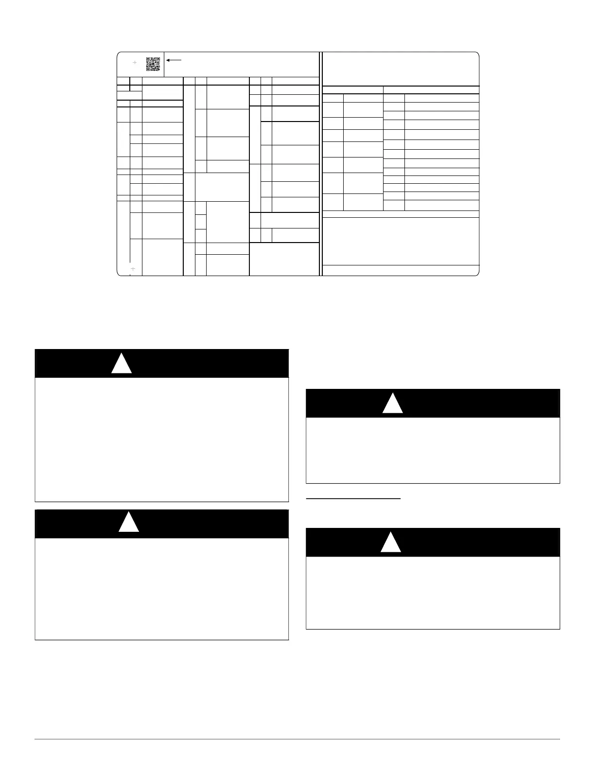
SERVICE LABEL
A210798
Fig. 59 – Service Label Information
START-UP, ADJUSTMENT, AND SAFETY
CHECK
General
1. Maintain 115-V wiring and ground. Improper polarity will result in
rapid flashing control diagnostic light and Status code (10.1) is
displayed. The furnace will NOT operate.
2. Make thermostat wire connections at the 24-V terminal block on
the furnace control. Failure to make proper connections will result
in improper operation.
3. Gas supply pressure to the furnace must be greater than 4.5-in. w.c.
(0.16 psig) but not exceed 14-in. w.c. (0.5 psig).
4. Check all manual-reset switches for continuity.
5. Natural gas service pressure must not exceed 0.5 psig (14- in. w.c.,
350 Pa), but must be no less than 0.16 psig (4.5-in. w.c., 1125 Pa).
6. Blower door must be in place to complete 115-V electrical circuit
and supply power to the furnace components.
Start-Up Procedures
1. Purge gas lines after all connections have been made.
2. Check gas lines for leaks.
3. To Begin Component Self-Test
a. Remove thermostat wire connected to R terminal on control to
ensure no thermostat demands are present.
b. Temporarily depress blower door switch to power the control
board to complete component self-test.
Flt
Last 7 faults that occured
CL
Cooling and Heat Pump Blower speed
CFn
Continuous Fan speed
Hod
Heat OFF delay
Cod
Cool OFF delay
Orientation upflow or downflow
inF
Ct
r5t
Dir
tnn
Twinning Main or Secondary
Program # and Software version
Component test
Ht
Heating Blower speed
Major Minor
Description
Description
Description
Major Minor
Major Minor
1
12
L1 polarity fault
W on at power up
Rapid flash
LED
1
10
1
13
Limit Lockout -
switch open longer
than 3 minutes in
Main Limit circuit
1
33
A switch has opened in
the Main Limit circuit.
34
Ignition fault - during
four consecutive
ignition trials.
2
After successful
ignition (flame proven)
flame loss before
heating blower on
delay.
After successful
ignition (flame proven)
flame loss after heating
blower on delay.
3
45
46
1
Control failure – flame
circuit fault, memory
mismatch or sequence
error.
2
Control failure – gas
valve relay will not
close.
3
1
Control failure
– EEPROM memory
issue.
For code 45, cycle power, if
code 45 repeats, replace
control.
Momentary loss of
power
31
1
21
22
23
False flame
1
Open Main pressure
switch (LPS)
32
1
1
24
Fuse fault
1
27
1
2
3
1
Stuck closed Main
pressure switch
2
Stuck closed
secondary pressure
switch
1
14
Ignition Lockout
after 4 consecutive
ignition tries
2
Flame lost 3 times
after 70s of heating
3
Lockout - 7 loss of
flame events during
a heat request
24VAC sensed on
gas valve when
shouldn’t be
25
No program info in
micro, no heating
operation.
Corrupted program
file, reprogram
control using service
app or super plug
(supplied
separately), no
heating operation.
1
2
Twinned units are
not identical,
program #'s do not
match. Ensure
furnaces are
identical (same
program #)
when twinning.
Main unit will not
operate heating.
3
4
5
6
7
Installer settings
corrupted.Try
reselecting installer
settings, or reprogram
control. Control will
operate using default
installer settings.
Wrong program for
control used -
reprogram control so
program matches
control used. No
heating operation.
Non-Condensing
program detected in
a Condensing model.
Program in super
plug is missing, not
recognized, or
corrupted. Remove
super plug then
retry. If still have 27
code, try a different
super plug. If still
fails, replace control.
If program in furnace control
is missing, not recognized,
or corrupted. Reprogram
Reprogram control with
correct program # as listed
on the rating plate.Replace
control if issue remains.
Main program invalid,
using backup program
to operate. Reprogram
control to correct
issue. Control still
operates normally.
2
Open secondary
pressure switch (HPS)
3
Secondary PS
Lockout - failed to
close secondary
PS after three trials
25
To initiate the component test sequence, the control must be in (idl) mode. No
thermostat demands (W, Y, G). Select component test (Ct) from menu select
buttons to start the component test sequence. Once initiated the furnace control
will perform the following sequence:
1. PUr- Inducer ON (remains ON for test).
2. HSI- After waiting 10s, HSI ON for 15 seconds.
3. Fn- After HSI, then Blower ON for 10 seconds.
4. End- After Blower, Inducer ON for 10 more
seconds.
The test ends.
COMPONENT TEST
MAIN MENU
All copyrighted materials used herein are the property of their
respective owners.
DISPLAY
DESCRIPTION
DISPLAY
DESCRIPTION
STATUS CODE TABLE
Scan QR code or reference troubleshooting guide in installation manual.
SYSTEM STATUS
CFn
bLr
Continuous Fan
Mode
Heat Pump Defrost
Mode
HPd
Cooling Mode
CL
Heating Mode
HT
Idle / Stand by
Mode
iDL
Active Status Code
Secondary Unit
Operating Blower
during CFn, CL,
or HT
##.#
MENU NAVIGATION
Scroll through main menu by pressing the MENU/SELECT button.
Press NEXT/OPTION button to view current setting (will flash on
display) and to scroll through setting options. Press
MENU/SELECT button to save new setting and return to main
menu. The display will flash to confirm setting selection before
returning to the main menu.
The major status code is displayed in the first 2 digits of the display. The minor status
code is displayed in the third digit . The major status code is also displayed on the
LED indicator through the door with the first digit being the number of short flashes
and the second digit being the number of long flashes.
Reset All Installer Settings to
Factory Defaults
idL,Ht,…
Current System Status
CAUTION
!
UNIT OPERATION HAZARD
Failure to follow this caution may result in intermittent unit operation
or performance dissatisfaction.
These furnaces are equipped with a manual reset limit switch in burner
assembly. This switch opens and shuts off power to the gas valve is an
overheat condition (flame rollout) occurs in the burner
assembly/enclosure. Correct inadequate combustion-air supply,
improper gas pressure setting, improper burner or gas orifice
positioning or improper venting condition before resetting switch. DO
NOT jumper this switch.
NOTICE
!
IMPORTANT INSTALLATION AND START-UP PROCEDURES
Failure to follow this procedure may result in a nuisance smoke or odor
complaint.
The manifold pressure, gas rate by meter clocking, temperature rise and
operation must be checked after installation. Minor smoke and odor
may be present temporarily after start-up from the manufacturing
process. Some occupants are more sensitive to this minor smoke and
odor. It is recommended that doors and windows be open during the
first heat cycle.
CAUTION
!
CUT HAZARD
Failure to follow this caution may result in personal injury.
Sheet metal parts may have sharp edges or burrs. Use care and wear
appropriate protective clothing, safety glasses and gloves when
handling parts and servicing furnaces.
WARNING
!
ELECTRICAL SHOCK HAZARD
Failure to follow this warning could result in personal injury, or death.
Blower access door switch opens 115-V power to control. No
component operation can occur unless switch is closed. Caution must
be taken. Do not touch uninsulated electrical components when
manually closing this switch for service purposes.