PG96MSA: Installation, Start-up, Operating and Service and Maintenance Instructions
Manufacturer reserves the right to change, at any time, specifications and designs without notice and without obligations.
51
NOTE:
1.A filter is required for each return-air inlet. Airflow performance included 3/4-in. (19 mm) washable filter media such as contained in a factory - authorized accessory filter rack. See
accessory list. To determine airflow performance without this filter, assume an additional 0.1 in. w.c. available external static pressure.
2.Adjust the blower airflow setting as necessary for the proper air temperature rise for each installation.
3.Airflows over 1800 CFM require bottom return, two-side return, or bottom and side return. A minimum filter size of 20” x 25” (508 x 635 mm) is required.
4.For upflow applications, air entering from one side into both the side of the furnace and a return air base counts as a side and bottom return
5..The -- entry indicates unstable operating conditions
66120D
1 Cont. Fan 720 610 490 390 290 205 110 - - -
2 800 695 590 480 390 300 220 135 - -
3 870 770 675 570 475 395 310 235 155 -
4 970 880 785 700 605 525 440 365 290 230
5 1060 975 890 805 725 635 555 485 410 345
6 1145 1070 985 905 830 750 665 595 525 455
7 1250 1175 1105 1025 955 880 805 730 660 595
8 1345 1280 1205 1135 1065 1000 930 860 785 725
9 1435 1370 1305 1240 1170 1105 1045 980 910 845
10 1545 1485 1425 1360 1300 1235 1175 1115 1050 990
11 1645 1590 1530 1475 1415 1350 1295 1240 1180 1125
12 1740 1685 1635 1580 1525 1465 1410 1355 1300 1250
13 1830 1775 1725 1675 1620 1565 1510 1455 1405 1355
14 Heat 2015 1965 1920 1870 1825 1775 1725 1680 1630 1580
15 2035 1990 1940 1895 1850 1805 1760 1710 1660 1615
16 2140 2095 2050 2005 1960 1915 1875 1830 1785 1740
17 2230 2190 2150 2110 2070 2025 1985 1945 1905 1860
18 Cooling 2425 2385 2340 2290 2240 2190 2135 2080 2025 1965
66140D
1 Cont. Fan 795 685 585 475 380 290 205 135 - -
2 900 795 700 605 505 420 340 260 180 -
3 960 865 775 685 590 500 420 345 265 195
4 1050 960 870 785 700 610 530 455 385 315
5 1160 1075 985 910 835 755 670 590 525 455
6 1260 1180 1100 1020 950 880 800 720 650 585
7 1355 1285 1205 1130 1060 995 925 855 775 705
8 1445 1375 1300 1230 1160 1095 1035 970 895 825
9 1545 1480 1415 1345 1280 1220 1155 1095 1035 965
10 1650 1585 1520 1460 1395 1330 1275 1215 1155 1100
11 1740 1680 1620 1560 1500 1435 1380 1320 1265 1210
12 1840 1785 1725 1670 1615 1555 1500 1445 1390 1340
13 1940 1885 1830 1775 1720 1670 1610 1555 1505 1450
14 2050 1995 1945 1890 1840 1790 1735 1680 1630 1575
15 Heat 2095 2040 1990 1940 1890 1840 1790 1735 1680 1630
16 2150 2100 2050 2000 1950 1905 1855 1800 1745 1695
17 2255 2205 2155 2110 2060 2015 1965 1915 1860 1810
18 Cooling 2420 2370 2325 2280 2230 2165 2095 2025 1955 1880
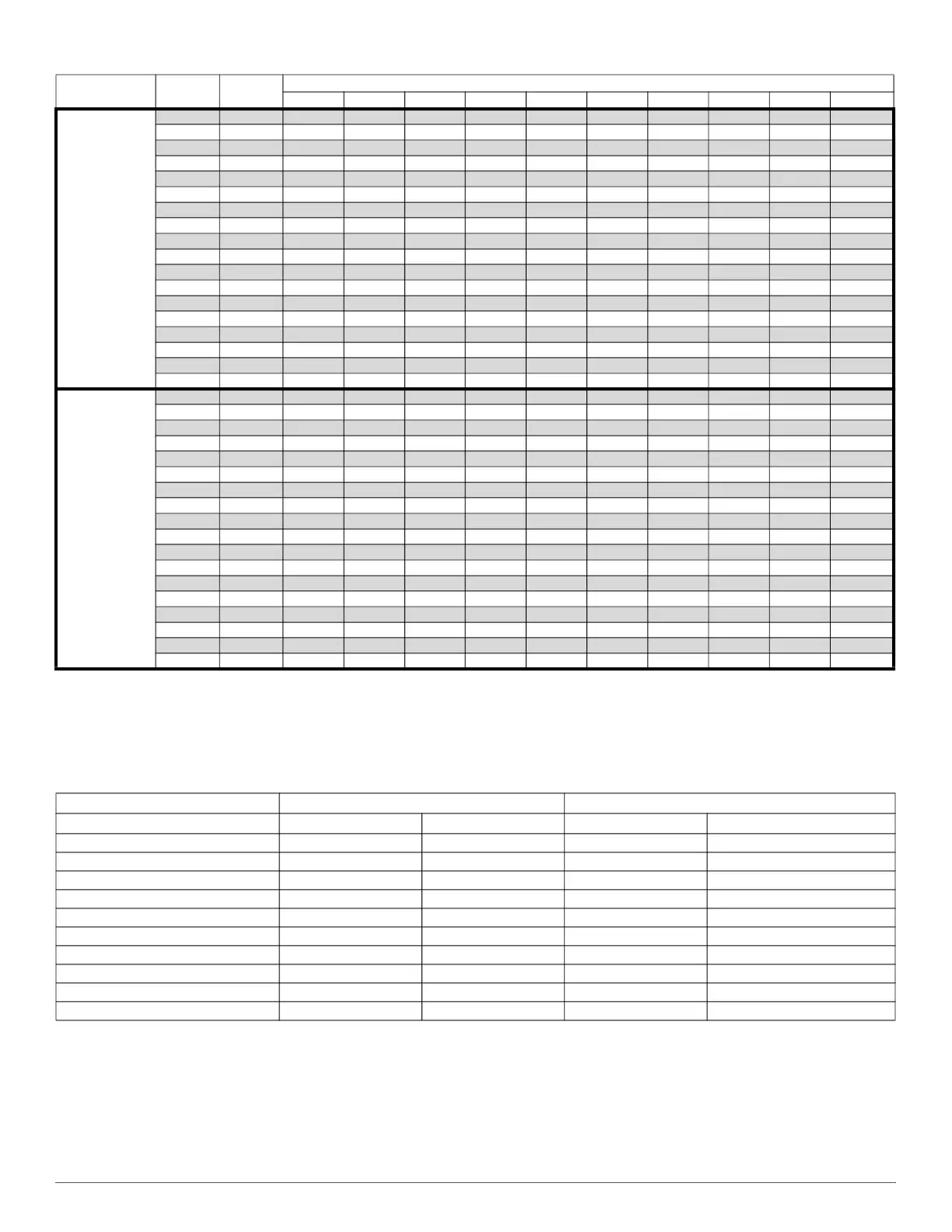
Table 18 – Air Delivery - CFM (with filter) (Continued)
Unit Size
Airflow
Setting
Default
Setting
External Static Pressure (IN.W.C.)
0.1 0.2 0.3 0.4 0.5 0.6 0.7 0.8 0.9 1
Table 19 – Airflow Settings
Default Airflow Settings
*
*. Setting #1 is the default setting for Constant Fan
Designated Airflow Settings
Unit Size Heating Cooling Heating Constant Fan
30026A 6 18 (5-14) (1-7)
30040A 9 18 (6-11) (1-1)
36040B 8 18 (5-9) (1-5)
36060A 12 18 (9-12) (1-3)
48060B 9 18 (5-10) (1-7)
48080B 12 18 (7-13) (1-1)
60080C 9 17 (5-11) (1-8)
60100C 12 18 (10-12) (1-4)
66120D 14 18 (11-14) (1-3)
66140D 15 18 (10-15) (1-1)