3
UNIT ARRANGEMENT AND ACCESS
General
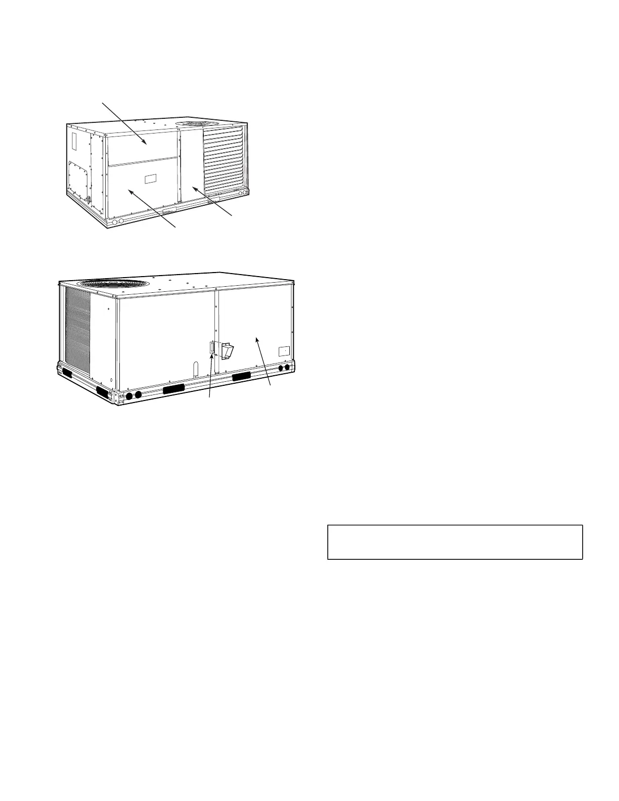
Figures 1 and 2 show general unit arrangement and access
locations.
Fig. 1 — Typical Access Panel Locations
Fig. 2 — Blower Access Panel Location
Routine Maintenance
These items should be part of a routine maintenance program, to
be checked every month or two, until a specific schedule for each
can be identified for this installation.
QUARTERLY INSPECTION (AND 30 DAYS AFTER INI-
TIAL START)
• Return air filter replacement
• Outdoor hood inlet filters cleaned
• Belt tension checked
• Belt condition checked
• Pulley alignment checked
• Fan shaft bearing locking collar tightness checked
• Condenser coil cleanliness checked
• Condensate drain checked
Seasonal Maintenance
These items should be checked at the beginning of each season (or
more often if local conditions and usage patterns dictate).
AIR CONDITIONING
• Condenser fan motor mounting bolts tightness
• Compressor mounting bolts
• Condenser fan blade positioning
• Control box cleanliness and wiring condition
• Wire terminal tightness
• Refrigerant charge level
• Evaporator coil cleaning
• Evaporator blower motor amperage
HEATING
• Heat exchanger flue passageways cleanliness
• Gas burner condition
• Gas manifold pressure
• Heating temperature rise
ECONOMIZER OR OUTSIDE AIR DAMPER
• Inlet filters condition
• Check damper travel (economizer)
• Check gear and dampers for debris and dirt
AIR FILTERS AND SCREENS
Each unit is equipped with return air filters. If the unit has an econ-
omizer, it will also have an outside air screen. If a manual outside
air damper is added, an inlet air screen will also be present.
Each of these filters and screens will need to be periodically re-
placed or cleaned.
RETURN AIR FILTERS
Return air filters are disposable fiberglass media type. Access to
the filters is through the small lift-out panel located on the rear
side of the unit, above the evaporator/return air access panel. (See
Fig. 1.)
To remove the filters:
1. Grasp the bottom flange of the upper panel.
2. Lift up and swing the bottom out until the panel disengages
and pulls out.
3. Reach inside and extract the filters from the filter rack.
4. Replace these filters as required with similar replacement fil-
ters of same size.
To re-install the access panel:
1. Slide the top of the panel up under the unit top panel.
2. Slide the bottom into the side channels.
3. Push the bottom flange down until it contacts the top of the
lower panel (or economizer top).
OUTSIDE AIR HOOD
Outside air hood inlet screens are permanent aluminum-mesh type
filters. Check these for cleanliness. Remove the screens when
cleaning is required. Clean by washing with hot low-pressure wa-
ter and soft detergent and replace all screens before restarting the
unit. Observe the flow direction arrows on the side of each filter
frame.
ECONOMIZER INLET AIR SCREEN
This air screen is retained by spring clips under the top edge of the
hood. (See Fig. 3.)
To remove the filter, open the spring clips. Re-install the filter by
placing the frame in its track, then closing the spring clips.
FILTER ACCESS PANEL
OUTDOOR-AIR OPENING AND
INDOOR COIL ACCESS PANEL
COMPRESSOR
ACCESS PANEL
BLOWER
ACCESS
PANEL
FLUE OPENING
IMPORTANT: DO NOT OPERATE THE UNIT WITHOUT
THESE FILTERS!
 Loading...


