26
provides a visual display of operational or sequential problems
when the power supply is uninterrupted. When a break in power
occurs, the IGC will be reset (resulting in a loss of fault history)
and the indoor (evaporator) fan ON/OFF times will be reset. The
LED error code can be observed through the viewport. During ser-
vicing refer to the label on the control box cover or Table 8 for an
explanation of LED error code descriptions.
If lockout occurs, unit may be reset by interrupting power supply
to unit for at least 5 seconds.
* A 3 second pause exists between LED error code flashes. If more
than one error code exists, all applicable codes will be displayed in
numerical sequence.
† Indicates a code that is not an error. The unit will continue to operate
when this code is displayed.
Orifice Replacement
This unit uses orifice type LH32RFnnn (where nnn indicates ori-
fice reference size). When replacing unit orifices, order the neces-
sary parts via Carrier RCD. See Table 10 for available orifice siz-
es. See Tables 11 and 12 for orifice sizes for Natural Gas and LP
fuel usage at various elevations above sea level.
Check that each replacement orifice is tight at its threads into the
manifold pipe and that orifice projection does not exceed maxi-
mum value. See Fig. 35.
Minimum Heating Entering Air Temperature
When operating on first stage heating, the minimum temperature
of air entering the dimpled heat exchanger is 50°F (10°C) continu-
ous and 45°F (7°C) intermittent for standard heat exchangers and
40°F (4°C) continuous and 35°F (2°C) intermittent for stainless
steel heat exchangers. To operate at lower mixed-air temperatures,
a field-supplied outdoor-air thermostat must be used to initiate
both stages of heat when the temperature is below the minimum
required temperature to ensure full fire operation. Wire the out-
door-air thermostat OAT (see Fig. 39) (part no. HH22AG106) in
series with the second stage gas valve (See Fig. 41.) Set the out-
door-air thermostat at 35°F (2°C) for stainless steel heat exchang-
ers or 45°F (7°C) for standard heat exchangers. This temperature
setting will bring on the second stage of heat whenever the ambi-
ent temperature is below the thermostat setpoint. Indoor comfort
may be compromised when heating is initiated using low entering
air temperatures with insufficient heating temperature rise.
Fig. 39 — OAT Connections
Troubleshooting Heating System
Refer to Tables 13 and 14 for additional troubleshooting topics.
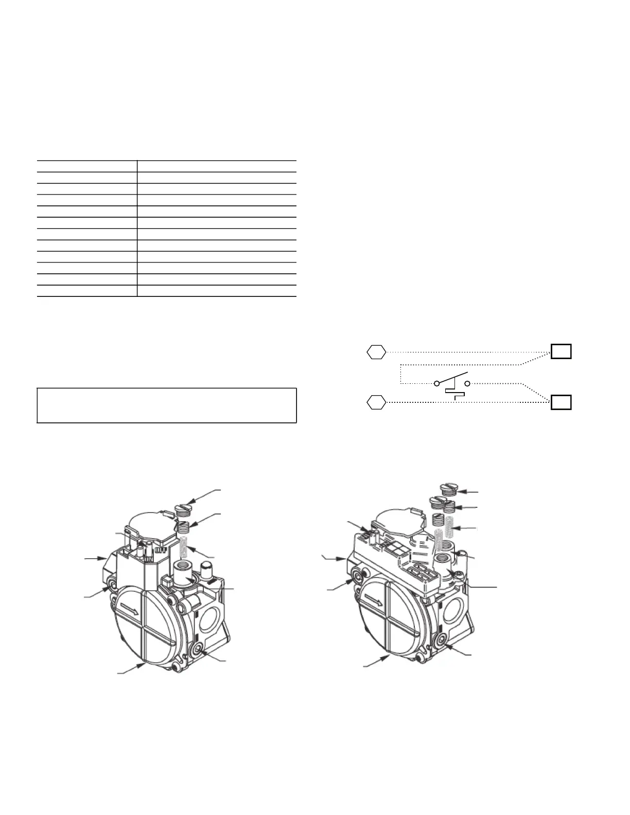
Fig. 40 — Gas Valves
Table 8 — LED Error Code Description
LED INDICATION ERROR CODE DESCRIPTION
On Normal Operation
Off Hardware Failure
1 Flash† Evaporator Fan On/Off Delay Modified
2 Flashes Limit Switch Fault
3 Flashes Flame Sense Fault
4 Flashes 4 Consecutive Limit Switch Faults
5 Flashes Ignition Lockout Fault
6 Flashes Induced-Draft Motor Fault
7 Flashes Rollout Switch Fault
8 Flashes Internal Control Fault
9 Flashes Software Lockout
LEGEND
LED — Light Emitting Diode
IMPORTANT: Refer to Troubleshooting Tables 13 and 14 for
additional information.
CTB
W2
Thermostat
TH1
TH2
W1
W1
W2
OAT
REGULATOR
COVER SCREW
PLASTIC ADJUST
SCREW
ON/OFF SWITCH
1/2" NPT INLET
INLET
PRESSURE
TAP
1/2" NPT OUTLET
MANIFOLD
PRESSURE TAP
GAS PRESSURE
REGULATOR
ADJUSTMENT
REGULATOR SPRING
(PROPANE - WHITE
NATURAL - SILVER)
ON/OFF SWITCH
1/2" NPT INLET
1/2" NPT OUTLET
INLET
PRESSURE
TAP
REGULATOR COVER SCREW
PLASTIC ADJUST SCREW
REGULATOR SPRING
(PROPANE - WHITE
NATURAL - SILVER)
MANIFOLD
PRESSURE TAP
LOW STAGE
GAS PRESSURE
REGULATOR ADJUSTMENT
SINGLE STAGE
2 STAGE
 Loading...


