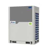
Carrier service manual R410a DC Inverter 60Hz
Installation
2.2.7 Mount the air deflector
When installing, takes off the mesh firstly, and then conduct in according of the following two schedules.
2.2.7.1 Installation of 8HP,10HP.
Schedule 1:
Schedule 2:
Note: 920mm=36-7/32in., 725mm=28-35/64in., 243mm=9-9/16in, 330mm=12-63/64in., 765mm=30-1/8in.,
393mm=15-15/32in., 960mm=37-51/64in., 300mm=11-13/16in., 250mm=9-27/32in., 3000mm=118-7/64in.,
100mm=3-15/16in., 940mm=37-1/64in., 90mm=3-35/64in., 10mm=25/64in., 760mm=29-59/64in.
Unit: mm
393
243 243330
243 243330
960
Radius
Air outlet louver dimension (optional)
C
D
A
B
725
100
10
10
12-Φ3.2
Remove the
iron filter first
12 ST3.9
self-threading screws
920
E
A≥300
θ≤15°
C≤3000
725≤D≤760
B≥250
E=A+725
Radius
E
Fig.4-23
Air outlet louver dimension (optional)
Radius
A
B
9
0
1
0
0
12-Φ3.2
940
920
725
765
393
960
330
243
243
C
12 ST3.9 self-threading screw
Remove the
iron filter firstly
Unit: mm
A≥300
θ≤15°
C≤3000
D=A+920
B≥250
Radius
D
 Loading...