ZS zone sensors
ZS Sensors Carrier Proprietary and Confidential CARRIER CORPORATION ©2017
Installation Guide All rights reserved
13
5 Strip about .25 inch (.6 cm) of the inner insulation from each wire.
6 If wiring 1 cable to the ZS Sensor, cut the shield wire off at the outer jacket, then wrap the cable with tape at
the outer jacket to cover the end of the shield wire.
If wiring 2 cables in a daisy-chain configuration, twist together the shield wires, then wrap the shield wires
with tape.
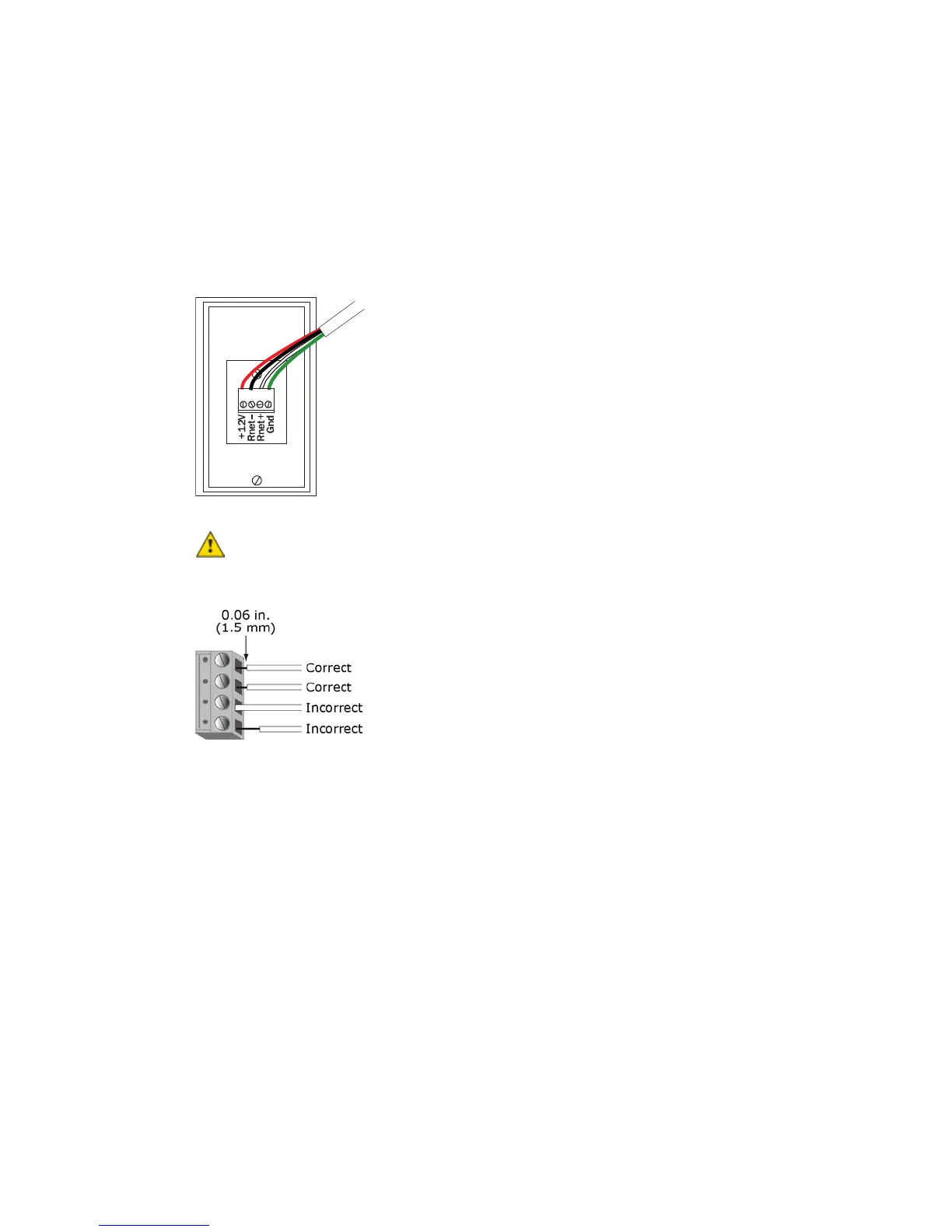
7 Insert the other 4 wires into the ZS Sensor's screw terminal connector. If wiring 2 cables, insert like-colored
wires into each terminal.
Carrier recommends that you use the
following Rnet wiring scheme:
Red
Black
White
Green
+12V
Rnet-
Rnet+
Gnd
Allow no more than 0.06 inch (1.5 mm) bare communication wire to protrude. If bare
communication wire contacts the cable's foil shield, shield wire, or a metal surface other than the terminal
block, the device may not communicate correctly.
8 Attach the sensor's cover and circuit board to the mounted backplate, inserting the top first.
9 Turn the setscrews one full turn counterclockwise so that the cover cannot be removed.
10 Turn on the controller's power.
Use the same polarity throughout the Rnet.
 Loading...