Introduction
Network Extender 3
User Guide
1-4
Network Extender Basics
This section will guide you through the basic features and functions of your Network
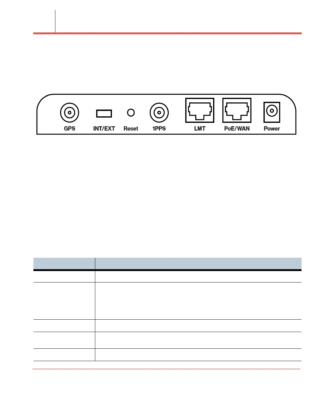
Extender. Figure 1-2 details the ports on the back of the Network Extender.
Figure 1-2. Network Extender Ports
The RF Antenna of Network Extender is embedded in the Front cover and 6 different
external antenna ports are located on the top of the Network Extender.
The included GPS antenna is required for the automated setup process and is
necessary in the event the mobile phone is used to call for emergency services while in
the coverage area of the Network Extender. Table 1-1 provides port information for
the Network Extender.
The Network Extender has multiple, single color LEDs used to indicate the device
connectivity status. Please refer to Chapter 5, Troubleshooting when attempting to
troubleshoot the solution.
Table 1-1. Network Extender port descriptions
Port Name Function
GPS To connect GPS antenna and receive GPS signal.
INT/EXT To select antenna INT (Internal)/EXT (External).
WARNING: Incorrect use of this switch may cause PA damage. Refer to INT/EXT
antenna (page 2-20) for important information on the proper use of the INT/EXT
switch.
Reset Factory Reset.
1PPS To connect 1PPS clock source (Iridium receiver or GPS receiver) and receive
1PPS signal.
LMT Local Monitoring Terminal Port to manage setting and display device status.
 Loading...