Manual No. 016-5032-006 19
Cab Component Installation
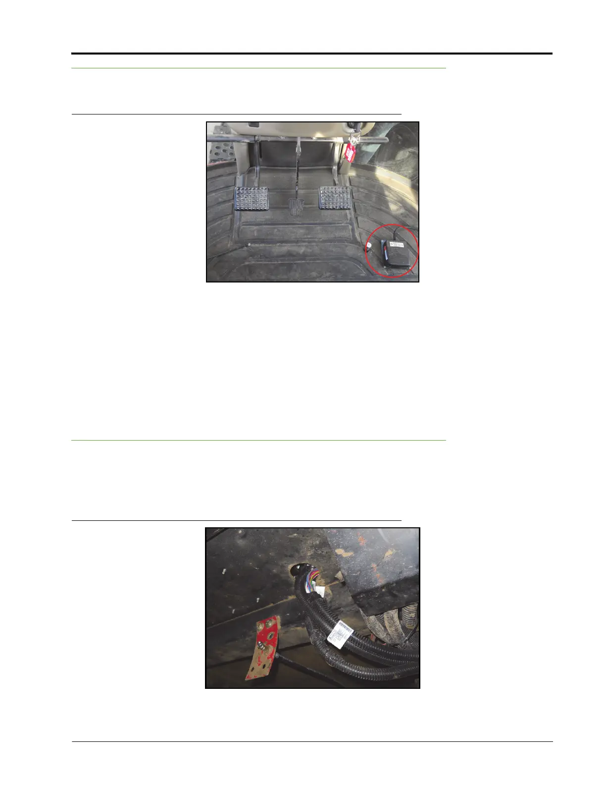
Install the Foot Switch
FIGURE 3. Foot Switch Installed
1. Select a suitable location for the foot switch (P/N 063-0172-470) to be installed.
Note: The foot switch should be installed in a location where the operator has easy access to it and is
able to fully press the pedal.
2. Using the holes in the foot switch as a template, drill holes in the floor of the cab.
3. Secure the foot switch to the floor by installing the supplied screws in each of the mounting holes.
4. Locate the ENABLE connector on the node harness and connect it to the foot switch cable connector.
Install the Valve Harness
1. Connect the 12-pin connector of the valve harness (P/N 115-4001-134) into the mating connector of the
node harness (P/N 115-4001-109).
FIGURE 4. Valve Cable Routing