Do you have a question about the Casio WK-3500 and is the answer not in the manual?
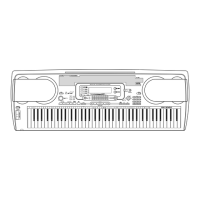
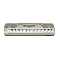
Details keyboard size, number of tones, and polyphony capabilities.
Covers Drawbar Organ, Effects, Auto Accompaniment, Memory, Demo Tunes, Synthesizer, Registration, Mixer.
Details MIDI, SMF Player, Flash Memory, Card Slot, Floppy Disk Drive, and Terminals.
Covers power supply, speaker output, dimensions, weight, and electrical characteristics.
Explains the key scanning mechanism and component mapping.
Lists and identifies the names and positions of keyboard keys.
Top and bottom view diagrams of the main PCB assembly.
Illustrates the layout of various sub PCBs, including MA2M and MA3M.
Diagram showing the component layout for the display PCB (JCM734-LCD1M).
Diagrams showing the layout of console (CN1M-CN7M) and keyboard PCBs.
Detailed schematic for the main PCB (M734-MA1M).
Schematics for sub PCBs (M734-MA2M/MA3M) and Display PCB (M734-LCD1M).
Schematics for console PCBs (CN1M to CN7M) and related connectors.
Procedure for removing the battery cover, battery, and upper case.
Instructions for removing PCBs and associated components.
Steps for removing control knobs, bender assembly, and connectors.
Procedure for removing the lower case and keyboard keys.
Steps to initiate the diagnostic program mode on the instrument.
Covers button functionality and initial system checks like AC adaptor detection.
Details checks for MIDI, sound source, ROM, RAM, DSP, and LEDs.
Covers LCD, card, bender, tuning meter, and APO checks.
Visual representation of all parts with their corresponding numbers.
Detailed list of components for the main PCB (MA1M).
List of parts for console PCBs (CN1M-CN7M) and keyboard PCBs.
Lists accessories, refurbish parts, and notes on part ordering.
| Brand | Casio |
|---|---|
| Model | WK-3500 |
| Category | Electronic Keyboard |
| Language | English |