INSTALLATION PROCEDURE FOR STANDARD 22” X 16” OPENING CONTINUED
7
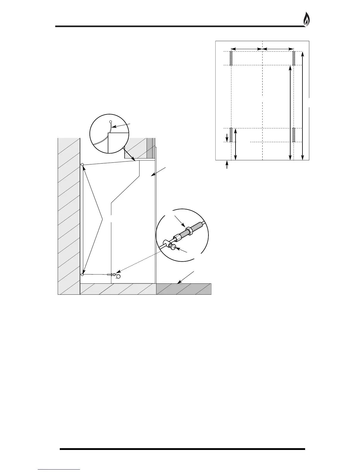
R
adiant box
Hearth
E
ye Bolts
Centre Line
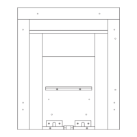
Drill Holes for 4 eye bolts
o
n 11
2mm centre lines
between max and min height.
6
5mm
m
in
Fix the radiant box into the opening, securing into position using the cable fixing kit (Fig. 6). Do not cut off the
loose ends as the full length is required should the radiant box need refitting at any time. Coil up and securely
store underneath the burner tray.
1. Position the burner tray into the box in order to determine the length of 8mm gas supply needed and cut to
length.
2. Before making the final connection, thoroughly purge the supply pipe to clear any foreign matter, i.e. masonry
dust etc, as this could lead to blockages in the control valve and/or pilot assemblies.
3. Fix the burner in place using the four screws and make the gas connection. Carry out a gas soundness test.
4. Ensure that the bulbous side of the I.R sensor is facing the front and is positioned around the ash pan area so
that there is a direct line of sight for the remote handset to operate correctly.
The sensor bracket can be
repositioned by loosening the retaining nut. Retighten the nut when adjustment is complete.
ALTERNATIVE FIXING METHOD
W
here the drilling of the back panel is not practical, an alternative
f
ixing method may be employed using the cable fixing kit provided.
Drill four holes in the rear of the fireplace opening (Fig. 5).
Securely fix the four eye bolts provided using suitable rawl plugs.
Feed one cable through each of the top holes in the rear of the
f
ire box.
1
15mm
max
5
00mm
min
5
50mm
m
ax
1
12mm
1
12mm
Tension Nut
Cable Clamping Screw
Fig. 5
Fig. 6
C
able