In order to access:
a. Pilot Assembly (including thermocouple)
b. Motorised Control Valve
c. Control Panel
It will be necessary to dismantle the burner tray. Please use the following procedure.
1. Ensure the appliance has fully cooled down.
2. Isolate gas supply.
3. Remove all the ceramic components off the fire and carefully placed to one side.
4. Working from the front of the fire, remove the lower fixing bracket screws and the two screws at the rear of the
tray
.
5. Disconnect the 8mm gas supply pipe using a 15mm spanner. This should then enable the burner to be
removed from its housing.
Break-down for access to components
1. Working from the front of the fire remove the two upper fixing point screws.
2. Remove the two pilot assembly screws.
3. Working from the rear of the burner tray, remove the two silencer bracket screws.
4. Slide the silencer (white ceramic block) upwards which will then give you open access to the main gas
injector
.
5. Remove the locking nut and washer using a 14mm spanner.
6. Remove the burner tray from the remote control housing. This should give you access to the two screws that
retain the heat shield to the remote base, thus giving unhindered access to all components.
7. Re-assembly is the exact reversal of the above procedure.
Note: When the batteries are becoming discharged, the fire will emit a continuous beeping sound. The
battery pack is held in place with a single screw, remove this screw and the pack can slide out.
Unclip the cover and replace the batteries with good quality alkaline or lithium - 6 x 1.5V AA
(Fig.14 - Page 16).
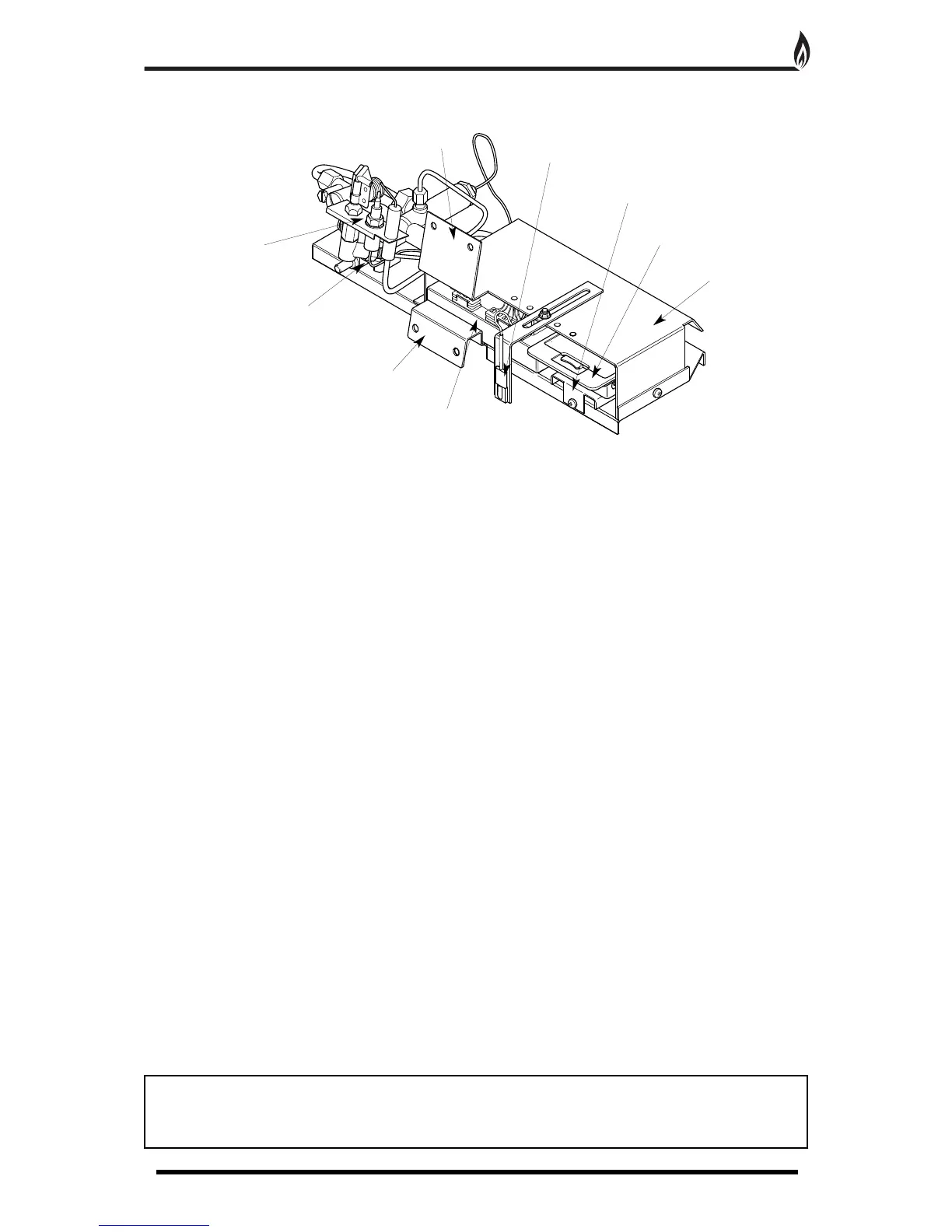
REMOTE CONTROL COMPONENT LAYOUT
1
1
Pilot assembly
Motorised valve
L
ower fixing point
Control panel
U
pper fixing point
I
.R. sensor
B
attery pack retainer
B
attery pack
Heat shield
Fig. 9