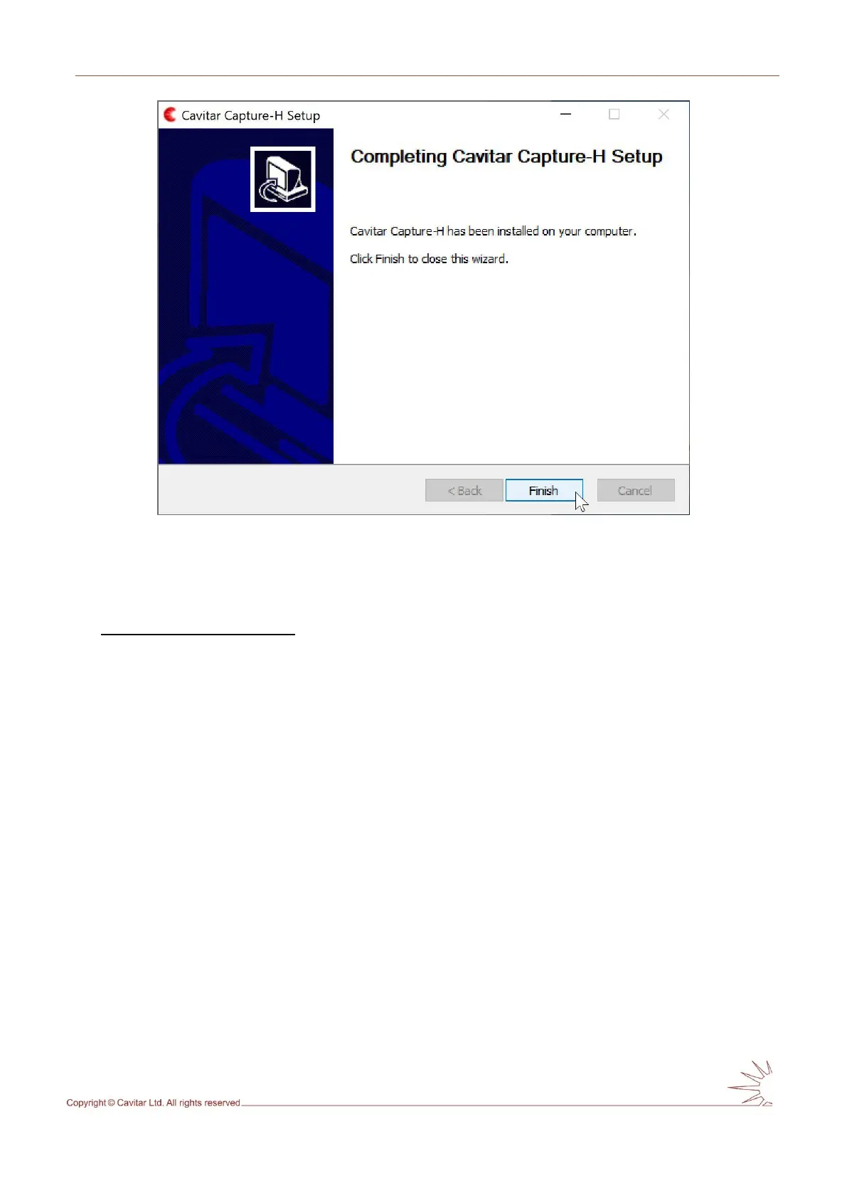
Fig. 4.8. Click “Finish” to complete installation.
4.2 Hardware installation
Installation of camera unit
The camera unit should be mounted or clamped with an appropriate fixture in such a way that
the object is located at the working distance of the camera unit. The mounting must enable
as efficient conductive (low ambient temperature or heat load from process) or active (high
ambient temperature or heat load from process) cooling of the camera unit as possible.
In case of conductive cooling, it is important to apply thermally conductive sheets between
the camera side(s) and the mounting as well as between the mounting and larger heat sink
(such as the body of machinery). Optimal thermally conductive sheets are offered by Cavitar
as optional accessories. It is also beneficial to maximize the area between camera side(s) and
mounting. The mounting should be made of material with high thermal conductivity (such as
aluminium).
If active cooling is applied, connect the cooling connectors (see Fig. 4.9H) to the threads of
the camera unit (see Fig. 3.3J, ensure the O-rings are in place; maximum torque 1 Nm) and
attach appropriate cooling system (air or liquid) to the connectors (suitable for hoses with
inner diameter of 6 mm). Always ensure that the cooling connectors and cooling hoses are
properly fastened and free from any leaks. Leaking cooling liquid can get in contact with
the back of the camera and may enter the camera, thus breaking the camera. Only use cooling
liquids and cooling equipment that can be in contact with aluminium (electro-chemical
corrosion must be prevented). The coolant must be sufficiently warm (e.g. 25-30 ˚C) to
avoid problems related to condensation. For more details, see Table 3.1 and the notes
related to it as well as the separate document “Guide for cooling”.