In Fig. 5.14 two red bars (1 and 2) can be seen in the “Current image” field. Bar 1 is at
grayscale value “0” and bar 2 is at grayscale value “255”. These grayscale values are set to
“0” and “255”, respectively, in the “Grayscale adjustment” field. Therefore they have no
effect. As an example, if one would move bar 2 to grayscale value “100” and keep the “Set to
grayscale value” for bar 2 at “255”, the grayscale range from 0…100 of the “Current image”
would be spread over the grayscale range 0…255 of the “Adjusted image”.
The number of bars can be also 3 or 4 (determined by selecting the desired value from the
“Number of bars” field). By using 3 bars one can e.g. assign the actual grayscale range of
0…50 to be displayed on screen as grayscale range 0…150 and the actual grayscale range of
51…150 to be displayed on screen as grayscale range 151…255. With 4 bars even more
detailed adjustment of grayscale ranges is possible. Once the adjusted image looks optimal,
the settings can be saved and the window can be closed by pressing “Set & Exit” button.
5.2.6 Guidelines
Up to four horizontal and up to four vertical guidelines can be drawn on top of the image.
These guidelines can be used for e.g. ensuring that the welding torch follows the correct path.
Together with the calibration feature (described in Section 5.2.7 in more detail) guidelines
also enable measurements from the images in real time.
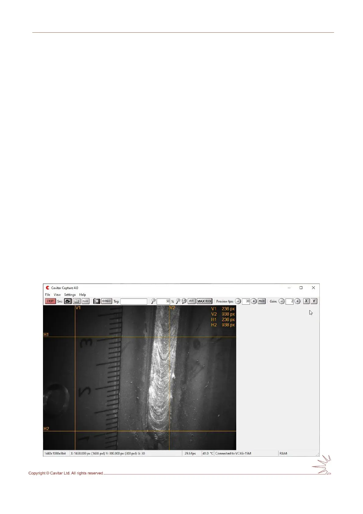
In order to add horizontal guidelines, click “X” button (see Fig. 5.10H). Vertical guidelines
can be added by clicking the “Y” button, respectively. The guideline options (Move, Lock and
Delete; Delete is only available for the latest horizontal and vertical line) can be selected by
pressing the left mouse button on top of the guideline. Fig. 5.15 shows the screen with four
guidelines.
Fig. 5.15. Guidelines.