19
LOAD CELL WIRING TO JUNCTION BOX
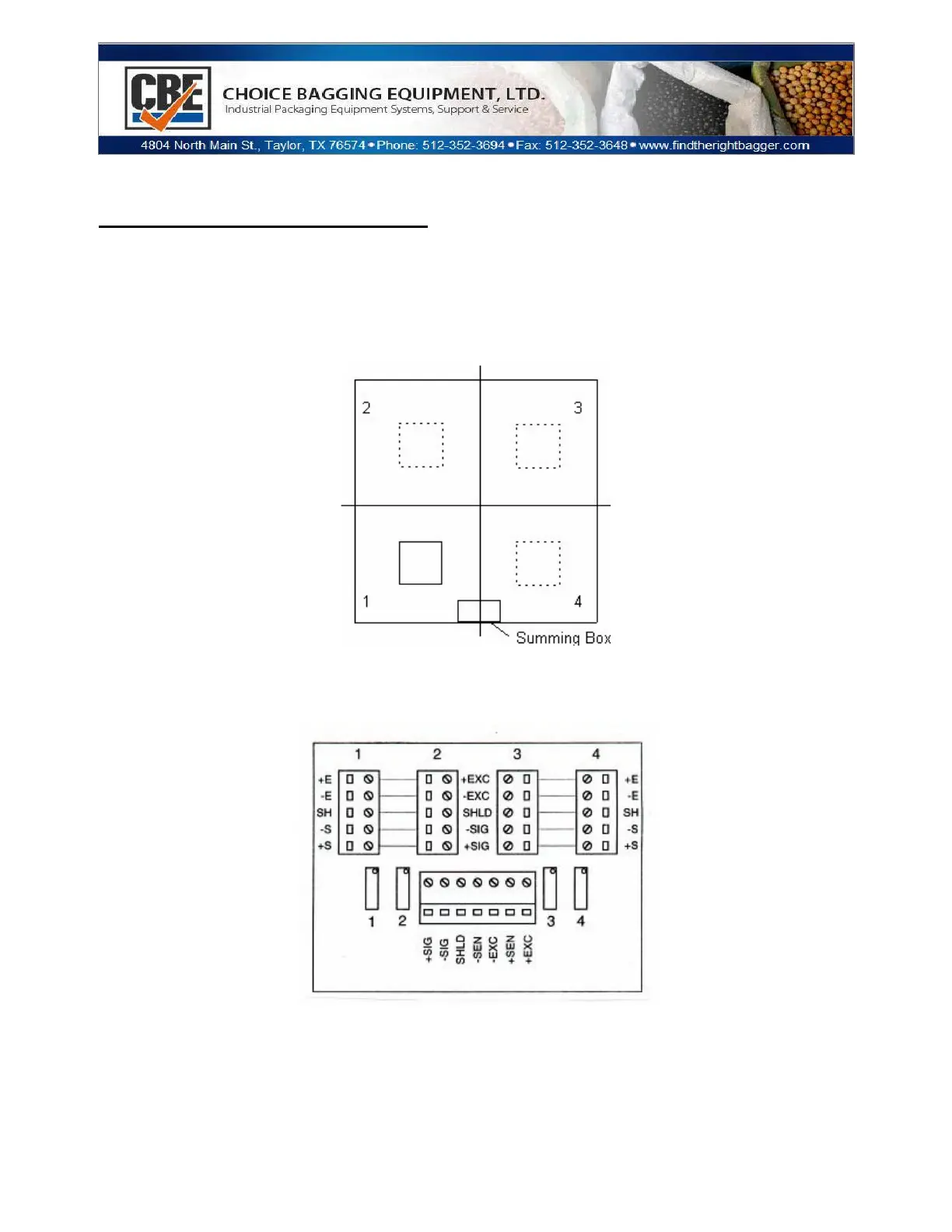
The four (4) load cells are each wired to their respective terminals in the junction box according to
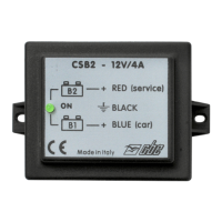
the corner numbering system shown in Figure 1 below. See Figure 2 (below) for junction box
layout and wiring connections. If equipped, tighten the strain relief hubs on the junction box with a
wrench to assure proper seal.
Figure 1: Load Cell Configuration
Figure 2: Junction Box Connections
Take the cable coming from the junction box of the 500 series and wire it to the controller indicator
as follows: