19
EASY PULSE METHOD
INPUT STORAGE
PROGRAMMED WELDING
Once the programme has been memo-
rized the operator can only weld with the
pre-set values and cannot change any
of the parameters. Go to
MANUAL
welding to make any changes.
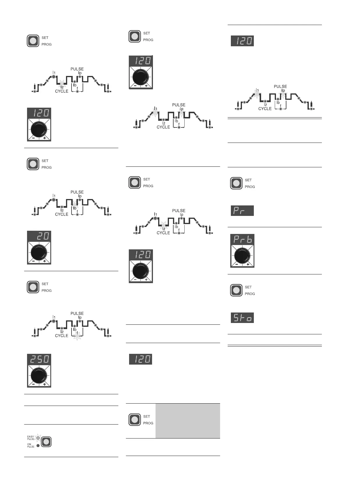
5A)
Press the
SET/PROG
key until the RED led of
the 2nd level of PEAK
CURRENT
I
2p
(5 ÷ 200
A) starts flashing
• Adjust the parameter by
turning the special dial
6A)
Press the
SET/PROG
key until the RED led of
the 1st level BASIC
CURRENT (5 ÷ 100 A)
starts flashing
• Adjust the parameter by
turning the special dial
7A)
Press the
SET/PROG
key until the RED led of
the PULSATION FRE-
QUENCY (0.5 ÷ 500
Hz) starts flashing
• Adjust the parameter by
turning the special dial
ATTENTION:
go on to point
8)
3B)
Press the "pulsation"
button until the
EASY
PULSE
function is
working
4B)
Press the
SET/PROG
key until the GREEN
led
I
1
and the RED led
I
p
will start flashing;
adjust the 1
st
level
PEAK CURRENT
I
1p
(5
÷ 200 A); value by tur-
ning the special dial.
ATTENTION:
with
EASY PULSE
working and adjusting the value of the
1st level PEAK CURRENT (
I
1p
) you will
have the values of the other 1st level
parameters (
I
1b
,
f
) in synergy
5B)
Press the
SET/PROG
key until the RED led of
the 2nd level PEAK
CURRENT
I
2p
(5 ¸ 200
A) starts flashing
• Adjust the parameter by
turning the special dial
ATTENTION:
adjusting the value of the
2nd level PEAK CURRENT (
I
2p
) while
EASY PULSE
is working, you will have
the values of the other 2nd level para-
meters (
I
2b
,
f
) in synergy
8)
If you want a test weld,
the led of the selected
parameter will flash
and the value of the
parameter being set
will be visualized on
the display while this is
being done
9)
Keep pressing the
SET/PROG
key for
more than 1 second to
leave the weld parame-
ter setting phase
10)
Use the
CYCLE
function for
PUL-
SATING TIG
welding
NOTE:
The RED LED
I
p
and the GREEN LED
I
1
remain on continuously
during the welding process
and the current value
being used for welding will
be visualized on the
display
ATTENTION:
The GREEN LED
I
1
must
be on continuously to enter the input
storage phase
1)
Keep pressing the
SET/PROG
key (for
about 3 seconds) until
the letters
Pr
appear
on the display
2)
Turn the dial to select
the number of the pro-
gramme where input
must be stored
3)
Keep pressing the
SET/PROG
key until
the letters
Sto
appear
on the display
4)
Input has been stored

 Loading...