8
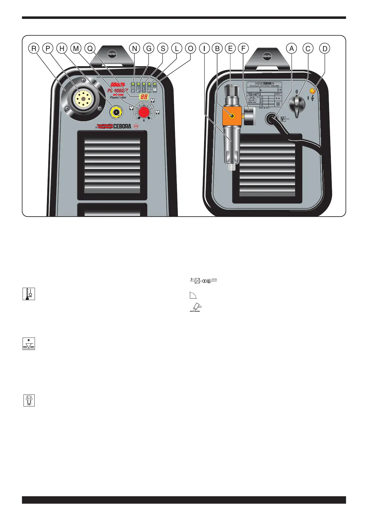
R) Safety guard
S) Blocked LED; lights when hazardous conditions
arise.
2.3 SAFETY DEVICES
This system comes equipped with the following safety
devices:
Overload cutout:
1) To avoid overloads during the pilot arc ignition and
during the cut. It is evidenced by the G led continu-
osly on (see fig.1).
2) Stop that the machine working at a room temperature
lower than -20°C. It is evidenced by the blinking G led
(see fig.1).
Pneumatic:
Located on the torch inlet to prevent low air pres-
sure. The LED L lights when tripped (see fig.1).
The blinking L led means that the pressure has temporar-
ily gone below 3.2 ÷ 3.5 bar.
Electrical:
1) Located on the torch body, to prevent hazardous volt-
ages from occurring on the torch when, swirl ring, elec-
trode or nozzle holder are replaced;
2) Blocks the equipment when the electrode is worn
to the point where it needs to be replaced. This
function is indicated when the LED N lights (fig.1). If this
safety device is tripped, shut off the machine before
replacing the electrode and nozzle. (Art. 356 only).
• Do not remove or short-circuit the safety devices.
• Use only original spare parts.
• Always replace any damaged parts of the machine
with original materials.
• Do not run the machine without its housings. This
would be dangerous to the operator and anyone else
in the work area, and would prevent the machine from
being cooled properly.
2.4 EXPLANATION OF TECHNICAL SPECIFICATIONS
EN60974.1 The machine has been built according to
EN 50199-92 this European standards.
N°..................... Serial number.
Always indicate this for any request regar
ding the machine.
....... Three-phase static frequency converter -
transformer/rectifier.
................... Drooping characteristic.
.................Suitable for plasma cutting.
TORCH TYPE........Type of torch that may be used with this
machine.
U
0
. PEAK........Secondary open-circuit voltage. Peak
value.
X....................... Percentage duty cycle.
The duty cycle expresses the percentage
of 10 minutes for which the machine may
work at a certain current I
2
and voltage
U
2
without overheating.
I
2
....................... Cutting current.
U
2
..................... Secondary voltage at cutting current I
2
.
On art. 354, this voltage is measured by
cutting with the nozzle in contact with
the workpiece, and on art. 356 by cutting
with the nozzle 3 mm away from the work
piece.
If this distance increases, the cutting
voltage also increases and the duty
cycle X% may drop.
U
1
......................Rated supply voltage
3~ 50/60Hz....... Three-phase 50-or 60-Hz power supply
I
1
....................... at the corresponding
cutting current I
2
and voltage U
2
.
IP23.................. Housing protection rating.
Fig.1