6. Once the 10" Saw Blade (part #14-I) is secured onto the Arbor Shaft (part #13-I),
replace the Throat Plate (part #15H) and tighten the Flat Head Screw (part #16H)
back in place. (See Figure Q, and Assy. Diagram H.)
To Attach The Blade Guard Assembly:
1. Unscrew and temporarily remove the Flat Head Screw (part #16H)) located at the
front of the Throat Plate (part #15H)). Then, remove the Throat Plate to expose
the 10" Saw Blade opening. (See Figures Q, R, and Assy. Diagram H.)
2. Place the Blade Guard Assembly (parts #1D Through 13D) over the Saw Blade
opening on the Saw Table (part #17H). (See Assy. Diagrams D, and H.)
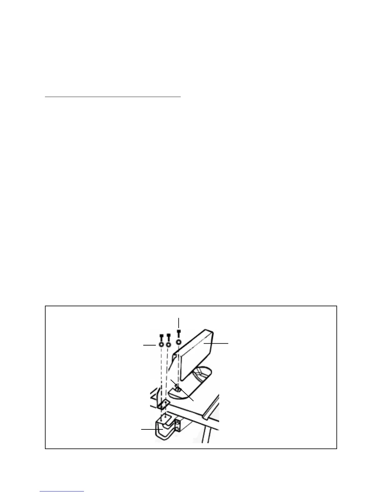
3. Insert two Socket Head Screws (part #5D) and two Washers (part #4D) in the two
holes at the back of the Riving Knife (part #6D. Tighten the two Socket Head
Screws, with Washers, into the Blade Guard Bracket (part #3-I).
(See Figure T, and Assy. Diagrams D, and I.)
4. Insert and tighten the third Socket Head Screw (part #5D) and one Washer (part
#4D) into the threaded mounting hole in the Saw Table (part #17H) under the
Throat Plate (part #15H). (See Figure T, and Assy. Diagrams D, and H.)
5. Once the Blade Guard Assembly (parts #1D through #13D) is secured onto the
Saw Table (part #17H), replace the Throat Plate (part #15H) and tighten the Flat
Head Screw (part #16H) back in place. (See Figure Q, and Assy. Diagram H.)
SOCKET HEAD SCREW(#5D)
BLADE GUARD (#10D)
R
IV
IN
G
K
N
IFE
(#6D
)
WASHER (#4D)
BLADE GUARD
BRACKET (#3-I)
FIGURE T
SKU 46813 PAGE 22