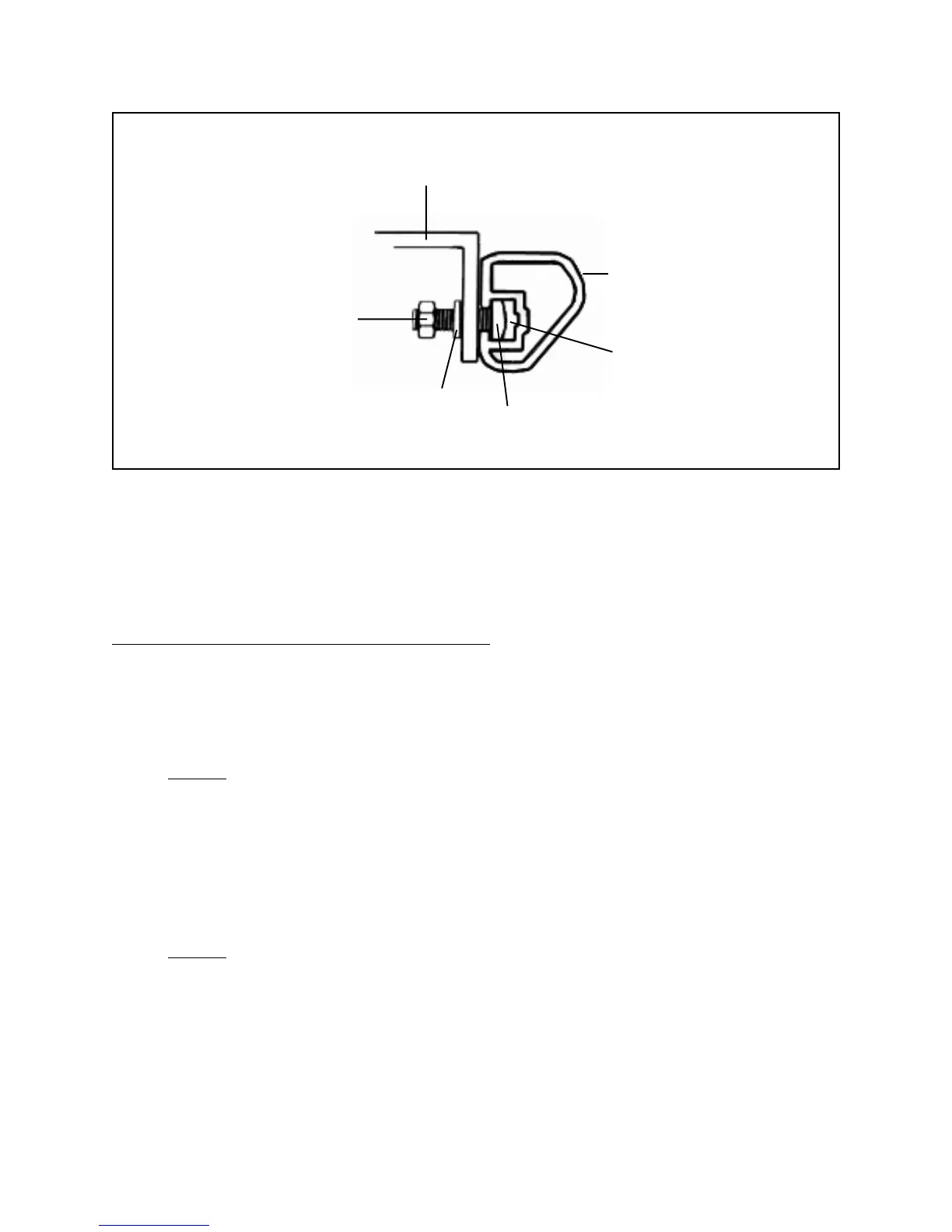
10” TABLE SAW/EXTENSION TABLES (#5H)
(REAR EDGES)
REAR RAIL (#3H)
SLOT
SQUARE HEAD
BOLT (#10H)
WASHER (#12H)
HEX NUT
(#13H)
FIGURE J
5. Wrench tighten all five Square Head Bolts (part #10H).
(See Figures I, J, and Assy. Diagram H.)
To Attach The Rip Fence And Miter Gauge:
1. Hook the Lock Block (part #7C) under the Rear Rail (part #3H). Then, lower the
front of the Rip Fence (part #10C) into the groove on the Front Rail (part #7H).
(See Figures K, L, and Assy. Diagrams C, and H.)
2. NOTE: The Rip Fence (part #10C) can be removed and reinstalled on the left
side of the 10" Table Saw. In this case, the Rip Fence Scale Indicator (part
#20C) can be repositioned on the left side of the Rip Fence by removing the
Semi-Circle Head Screw (part #22C) and Star Washer (part #21C). Then
reposition the Rip Fence Scale Indicator, and secure it with the Semi-Circle Head
Screw and Star Washer. (See Figures K, L, and Assy. Diagrams C, and Assy.
Diagram H.)
3. NOTE: To attach the Miter Gauge Assembly (parts #1A through 12A), simply
slide the Miter Gauge Rod (part #10A) into the right or left slot (nearest the Saw
Blade opening, on the Saw Table (part #17H).
(See Figure B, and Assy. Diagrams A, and H.)
SKU 46813 PAGE 15
 Loading...