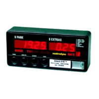
S700 Taximeter Operating & Programming Guide
6
Programming via Switches
Programming via switches is available in programming mode. User must remove wire-seal, seal cover and screw on the front right hand side of the
taximeter to access the programming switch. User needs to slide programming switch to the left position from Vacant state. After finishing
programming, it is important to slide programming switch to the right hand position to Vacant state and let meter restart. Do not disconnect power
before meter restarts properly. For more details about programming mode, refer to section “Programming Mode”.
ESI – Electronic Sealing of the Installation
The ESI provides a two-way electronic seal between the meter and the vehicle-mounting bracket. Once an electronic link has been initialized
between a meter (A) and a vehicle-mounting bracket (B), the ESI ensures that taximeter (A) will operate only in vehicle-mounting bracket (B) and no
other meter will operate in bracket (B). A meter that was never initialized to a vehicle mounting bracket or a meter that is plugged into a vehicle
mounting bracket to which it is not initialized will be disabled (the HIRED legend blinks on/off), i.e. it will not be able to run any trip. Establishing an
ESI link requires the removal of the meter’s wire-seal, seal cover and screw. With the meter in the harness, perform the following steps:
1) Go to program mode by sliding programming switch SW7 to the left position.
2) If the password option is enabled, the correct password has to be entered in group 6, item 1.
3) Go back to Vacant mode by sliding programming switch to the right hand position and the meter is now linked to the bracket.
It is important not to disconnect power before meter restarts properly.
Edit Data
Data editing is allowed in the following cases:
In program mode
In some of the menu items
In stats mode, when the reset code is required to clear stats
Upon entering data editing mode, the rightmost digit in the fare display starts to flash. The flashing digit indicates the digit position to be edited. This
digit can be incremented by pressing switch 4 or decremented by pressing switch 3. With binary values, pressing either switch 3 or 4 will toggle the
digit between 0 and 1. With decimal digits, switches 3 and 4 will scroll through the digits 0 through 9 in round robin fashion decrementing and
incrementing respectively.
Pressing switch 2 moves one digit to the left, and switch 5 one digit to the right, allowing any digit to be edited as described above.
Pressing switch 6 will save or enter data shown in the fare display.
Pressing switch 1 will abort editing without saving or entering data.
Menu Mode
From the Vacant state, press switch 4 to enter menu mode. Upon entering menu mode, all the legends become off, and the first menu number
flashes in the rate display. If the S700 is configured for audit trail, the first menu number displayed will be 0, otherwise it will be 1. While in menu
mode with menu number flashing, press switch 4 to increment through the menu list, or press switch 3 to decrement through the menu list.
SWITCH DEFINITION - MENU MODE
Exit To Top Level Of Current Menu
Abort Edit Data And Return To Top Level Of Current Menu
5
Move One Digit To The Right
6
7
NOTES: 5. Only available in AUDIT TRAIL MENU, ITEMS 3-5 (must press and hold for 2 seconds), and CONFIGURATION MENU, except ITEM 7.
6. Only available in AUDIT TRAIL MENU, ITEM 5.
7. Calibration test when in CALIBRATION MENU, or display test in DISPLAY MENU.