page 46 www.centsys.com
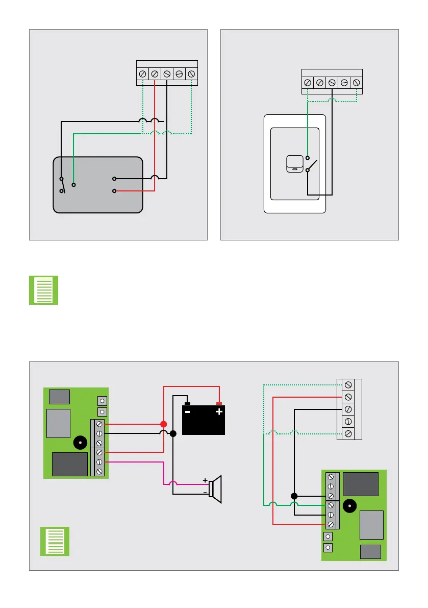
FIGURE 82. WIRING A UNIVERSAL
RECEIVER TO THE
SDO4 SMART
FIGURE 83. HARD-WIRING A WALL
SWITCH TO THE
SDO4 SMART
FIGURE 84. ANTI-TAMPER ALARM WIRING WITH TWO WIZOS
Hard-wired
wall switch
Universal
receiver
GND
24V +
COM
N/O
N/OCOM
ELECTRICAL SETUP OF ACCESSORIESSECTION 7
+24V
+24V
IO2
IO2
COM
COM
SB
SB
IO1
IO1
• The trigger/TRG (green wire) in Figures 82, 83 and 84 can be either wired
into IO1 or IO2, depending on the sites individual needs
• IO1 and IO2 can be congured using the MyCentsys Pro mobile application
• IO1 is congured as trigger/TRG by default
WiZo 1’s INPUT is linked
to WiZo 2’S OUTPUT.
+24V
IO2
COM
SB
IO1
Two WiZo-Link wireless modules may be connected to the system for a signal to be
wirelessly relayed to a third party alarm in the event that the anti-tamper input is
triggered.
WiZo 1
(Inside SDO4 SMART)
WiZo 2
(
Inside House)
SDO4 SMART
+12-24V DC
+12-24V DC
GND
GND
IN
COM
COM
NO
12V DC Lead
Acid Battery
Siren