4-16
06 VMN LOW
Condition for error detection
Failure in the VMN test.
The test begins at the switching on; check the connections of the 3 supplying cables from the logic unit to
the traction motor, the status of the cables and the status of the coil of the CT2 contactor (45 Ohm). If the
coil is interrupted the truck will signal the alarm at the switching on. If the coil value is ok, proceed
following one of the test below described in order to establish if the failure is produced by a cause
internal or external to the logic:
TEST 1
• Operate the parking brake and switch off the machine
• Open the compartment and disconnect the battery
• Check the power cables on the motor are tight
• Check the power cables on the logic unit are tight
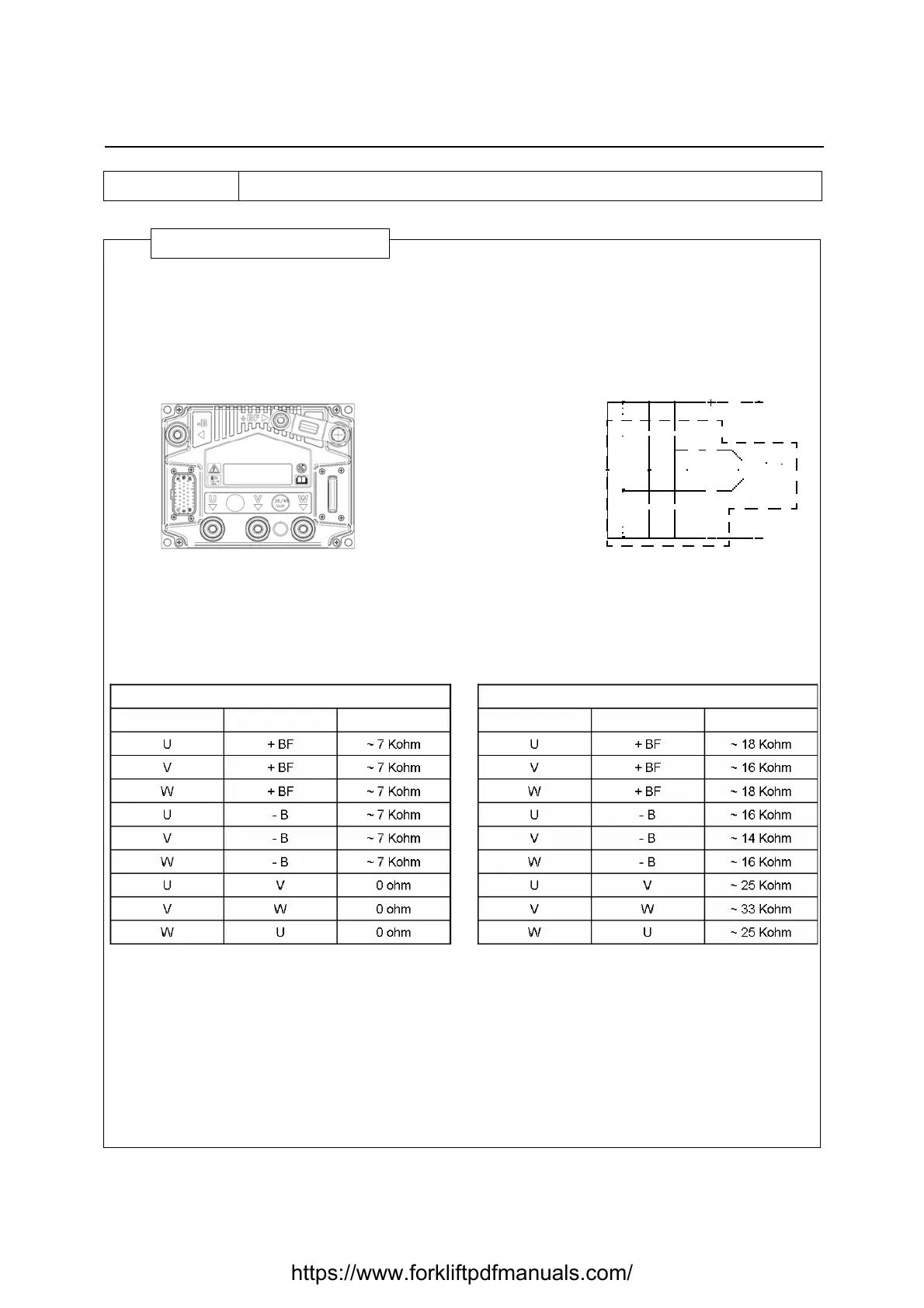
• Check the continuity values between the following points on the control unit using a tester:
Self-diagnostic
Connect the drive logic unit to the pump motor and check whether the display shows the alarm code
"06".
YES: replace the logic unit
If alarm “36“ appears check the motor state (see paragraph INSULATION CONTROL PROCEDURE and
MOTOR WINDING CONTROL PROCEDURE)
Values on the control with connected motor Values on the control with disconnected motor
Red cap Black cap Resistance Red cap Black cap Resistance
If very different values are measured compared to
those referred to in the above table,
disconnect all the power cables from the logic unit and
repeat the measurements
If an open circuit is detected, replace the logic
unit
https://www.forkliftpdfmanuals.com/