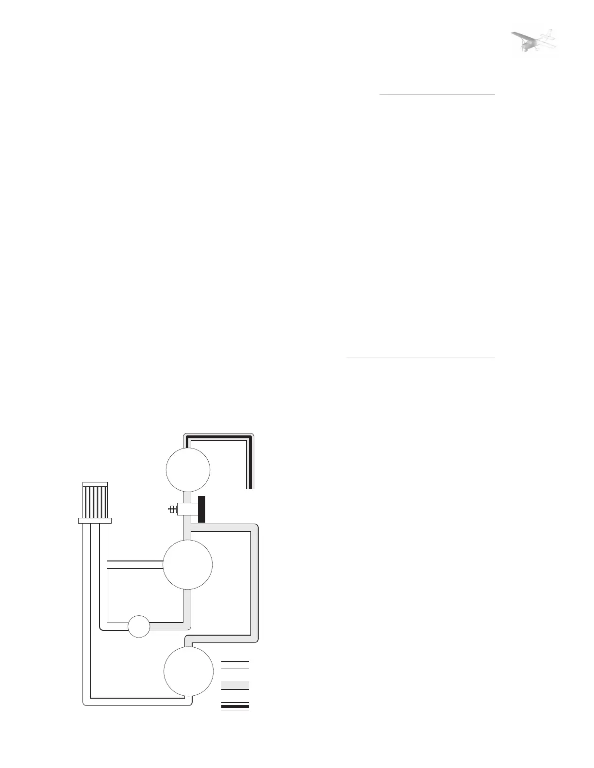
vacuum system
air filter
vacuum
pump
overboard
vent line
attitude
indicator
directional
indicator
suction
gage
vacuum relief
valve
inlet air
vacuum
discharge air
PITOT STATIC SYSTEM AND INSTRUMENTS
The pitot-static system supplies
ram air pressure to the airspeed
indicator and static pressure to
the air speed indicator, vertical
speed indicator and altimeter.
The system is composed of either
an unheated or heated pitot tube
mounted on the lower surface of
the left wing, an external static
port on the lower left side of the
forward fuselage, and the
associated plumbing necessary
to connect the instruments to the
sources. The heated pitot system
(if installed) consists of a heating
element in the pitot tube, a rocker
switch labeld PITOT HT, a 5-amp
circuit breaker, and associated
wiring.
A static pressure alternate source
valve may be installed on the
switch and control panel below
the throttle, and can be used if
the external static pressure source
is malfunctioning.
AIRSPEED INDICATOR
The airspeed indicator is
calibrated in knots. Limitation
and range markings include the
white arc, green arc, yellow arc
and a red line.
VERTICAL SPEED INDICATOR
The vertical speed indicator
depicts airplane rate of climb and
descent in feet per minute. The
pointer is actuated by
atmospheric pressure changes
resulting from changes of altitude
as supplied by static source.
ALTIMETER
Airplane altitude is depicted by
a barometric type altimeter. A
knob near the lower left portion
of the indicator provides
adjustment of the instrument‘s
barometric scale to the current
altimeter setting. •
VACUUM SYSTEM AND INSTRUMENTS
An engine-driven vacuum system
provides the suction necessary
to operate the attitude indicator
and directional indicator. The
system consistes of a vacuum
pump mounted on the engine, a
vacuum relief valve and vacuum
system airfilter on the left side
of the firewall below the
instrument panel, and
instruments on the left side of
the instrument panel.
ATTITUDE INDICATOR
The attitude indicator gives a
visual indication of flight attitude.
Bank attitude is presented by a
pointer at the top of the indicator
relative to the bank scale which
has index marks at 10°, 20°, 30°,
60° and 90° either side of the
center mark. Pitch and roll
attitudes are presented by a
miniature airplane superimposed
over a symbolic horizon area
divided into two sections by a
white horizon bar.
DIRECTIONAL INDICATOR
A directional indicator displays
airplane heading on a compass
card in relation to a fixed
simulated airplane image and
index. The indicator will precess
slightly over a period of time.
Therefor the compass card should
be set in accordance with the
magnetic compass just prior to
takeoff, and occasionally re-
adjusted on extended flights.
SUCTION GAGE
The suction gage is calibrated in
inches mercury and indicates
suction available for operation of
the attitude and directional
indicators. •
FLIGHT SIMULATION USE ONLY
AIRPLANE & SYSTEMS DESCRIPTION
PAGE 7
SECTION: | 1 | 2 | 3 | 4 | 5 | 6 | SUPP |