ceptions
to this are the optional
clock,
flight hour
recorder,
and battery
contactor
closing
(external
power)
circuits which
have
fuses
mounted
adjacent
to the battery.
Also,
the
cigar
lighter is
protected
by a man-
ually
reset
type circuit
breaker
mounted directly on the
back
of the lighter
behind the instrument panel.
When
more
than one radio is installed, the radio transmitter relay
(which is a part of the radio installation) is
protected
by the navigation
lights circuit
breaker
labeled
NAV LTS. It is important to
remember
that
any malfxmction in the navigation lights
system
which
causes
the cir-
cuit
breaker
to
open
will
de-activate
both the navigation lights and the
transmitter
relay. In this
event,
the navigation light switch should be
turned off to
isolate
the circuit; then
reset
the circuit
breaker
to re-
activate the transmitter relay and permit its
usage.
Do not
turn
on the
navigation lights switch
until
the malfunction has
been
corrected.
LIGHTING
EQUIPMENT.
EXTERIOR
LIGHTING.
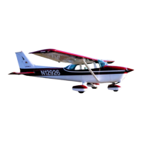
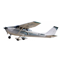
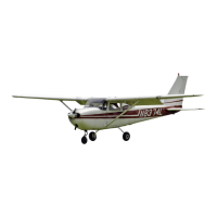
Conventional navigation lights are
located
on the wing tips and top of
the rudder. Optional lighting
includes
a
single
landing light in the
cowl
nose
cap, a flashing
beacon
on the top of the vertical fin, a
strobe
light
on
each
wing tip, and two
coiu-tesy
lights, one under
each
wing, just out-
board
of the cabin
door.
The
courtesy
lights are controlled by the
dome
light
switch
located
on the
overhead
console.
All other exterior lights are
controlled by
rocker
type
switches
located
on the left switch and control
panel. The
switches
are ON in the up position and OFF in the
down
po-
sition.
The flashing
beacon
should not be
used
when flying through
clouds
or
overcast;
the flashing light
reflected
from water
droplets
or particles in
the
atmosphere,
particularly at night, can
produce
vertigo and
loss
of
orientation.
The two high intensity
strobe
lights
will
enhance
anti-
collision pro-
tection.
However,
the lights should be turned off when taxiing in the
vicinity
of other aircraft, or during flight through
clouds,
fog or
haze.
2-6



 To Next Page