control knob located
below
the
wing flap switch should
be
opened, thereby
supplying static pressure from
the
cabin. Cabin pressures
will
vary,
however, with open cabin ventilators
or
windows.
The
most
adverse com-
binations
will
result
in
airspeed and altimeter variations
of no
more
than
2 MPH and
15
feet,
respectively.
RADIO
SELECTOR SWITCHES
^
RADIO SELECTOR SWITCH OPERATION.
Operation
of the
radio equipment
is
normal
as
covered
in the
respec-
^ tive radio manuals.
When
more
than
one
radio
is
installed,
an
audio
switching
system
is
necessary.
The
operation
of
this switching system
is
^ described below.
^
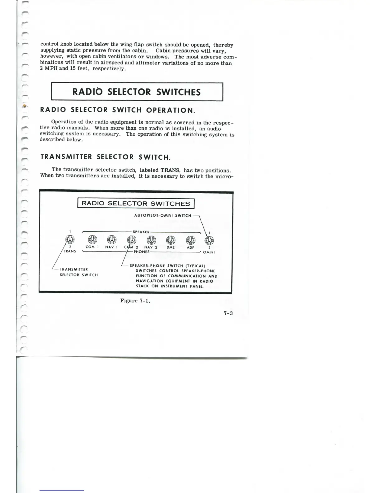
TRANSMITTER
SELECTOR SWITCH.
The transmitter selector switch, labeled TRANS,
has two
positions.
When
two transmitters are installed,
it is
necessary
to
switch
the
micro-
\O
SELECTOR
SWITCHEJ"]
AUTOPILOT-OMNI SWITCH
-SPEAKER-
COM
I NAV 1 COM 2 NAV 2 DME
TRANS
-PHONES-
OMNI
L
TRANSMITTER
SELECTOR SWITCH
SPEAKER-PHONE SWITCH (TYPICAL)
SWITCHES CONTROL SPEAKER-PHONE
FUNCTION OF COMMUNICATION AND
NAVIGATION
EQUIPMENT IN RADIO
STACK
ON
INSTRUMENT
PANEL
Figure
7-1.
7-3



 To Next Page