EasyManua.ls Logo

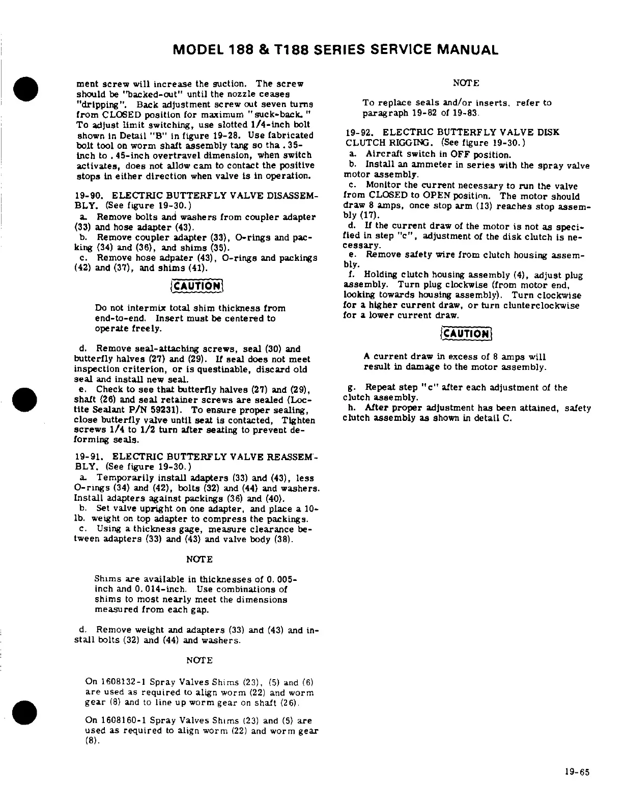
Cessna T188C - Electric Butterfly Valve Disassembly; Electric Butterfly Valve Reassembly; Electric Butterfly Valve Disk Clutch Rigging

Cessna T188C
624 pages
Print Icon
To Next Page IconTo Next Page
To Previous Page IconTo Previous Page
Loading...
MODEL
188
&
T188
SERIES
SERVICE
MANUAL
ment
screw
will
increase
the
suction.
The
screw
NOTE
should
be
"backed-out"
until
the
nozzle
ceases
"dripping".
Back
adjustment
screw
out
seven
turns
To
replace
seals
and/or
inserts,
refer
to
from
CLOSED
position
for
maximum
"suck-back.
"
paragraph
19-82
of
19-83
To
adjust
limit
switching,
use
slotted
1/4-inch
bolt
shown
in
Detail
"B"
in
figure
19-28.
Use
fabricated
19-92.
ELECTRIC
BUTTERFLY
VALVE
DISK
bolt
tool
on
worm
shaft assembly
tang
so
tha.
35-
CLUTCH
RIGGING.
(See
figure
19-30.)
inch
to
.45-inch
overtravel
dimension,
when
switch
a
Aircraft
switch
in
OFF
position.
activates,
does
not
allow
cam
to
contact
the
positive
b.
Install
an
ammeter
in
series
with
the
spray
valve
stops
in
either
direction
when
valve
is
in
operation.
motor
assembly.
c.
Monitor
the
current
necessary
to
run
the
valve
19-90.
ELECTRIC
BUTTERFLY
VALVE
DISASSEM-
from
CLOSED
to
OPEN
position.
The
motor
should
BLY. (See
figure
19-30.)
draw
8
amps,
once
stop
arm
(13)
reaches
stop
assem-
a.
Remove
bolts
and
washers
from
coupler
adapter
bly
(17).
(33)
and
hose
adapter
(43).
d.
If
the
current
draw
of
the
motor
is
not
as
speci-
b.
Remove
coupler
adapter
(33),
O-rings
and
pac-
fied
in
step
"c",
adjustment
of
the
disk
clutch
is
ne-
king
(34)
and
(36),
and
shims
(35).
cessary.
c.
Remove
hose
adpater
(43),
O-rings
and
packings
e.
Remove
safety
wire
from
clutch
housing
assem-
(42)
and
(37),
and
shims
(41).
bly.
f.
Holding
clutch
housing
assembly
(4),
adjust
plug
CAUTION
assembly.
Turn
plug
clockwise
(from
motor
end,
looking
towards
housing
assembly).
Turn
clockwise
Do
not
intermix
total
shim
thickness
from
for
a
higher
current
draw,
or
turn
clunterclockwise
end-to-end.
Insert
must
be
centered
to
for
a
lower
current
draw.
operate
freely.
CAUTION
d.
Remove
seal-attaching
screws,
seal
(30)
and
butterfly
halves
(27)
and
(29).
If
seal
does
not
meet
A
current
draw
in
excess
of
8
amps
will
inspection
criterion,
or
is
questinable,
discard
old
result
in
damage
to
the
motor
assembly.
seal
and
install
new
seal.
e.
Check
to
see
that
butterfly
halves
(27)
and
(29),
g.
Repeat
step
"c"
after
each
adjustment
of
the
shaft
(26)
and
seal
retainer
screws
are
sealed
(Loc-
clutch
assembly.
tite
Sealant
P/N
59231).
To
ensure
proper
sealing,
h.
After
proper
adjustment has
been
attained,
safety
close butterfly
valve
until
seat
is
contacted,
Tighten
clutch
assembly
as
shown
in
detail
C.
screws
1/4
to
1/2
turn
after
seating
to
prevent
de-
forming
seals.
19-91.
ELECTRIC
BUTTERFLY
VALVE
REASSEM-
BLY.
(See
figure
19-30.)
a.
Temporarily
install
adapters
(33)
and
(43),
less
O-rings
(34)
and
(42),
bolts
(32)
and
(44)
and
washers.
Install
adapters
against
packings
(36)
and
(40).
b.
Set
valve
upright
on
one
adapter,
and
place
a
10-
lb.
weight
on
top
adapter
to
compress
the
packings.
c.
Using
a
thickness
gage,
measure
clearance
be-
tween
adapters
(33)
and
(43)
and
valve
body
(38).
NOTE
Shims
are
available
in
thicknesses
of
0.
005-
inch
and
0.
014-inch.
Use
combinations
of
shims
to
most
nearly
meet
the
dimensions
measured from
each
gap.
d.
Remove
weight
and
adapters
(33)
and
(43)
and
in-
stall
bolts
(32)
and
(44)
and
washers.
NOTE
On
1608132-1
Spray
Valves
Shims
(23),
(5)
and
(6)
are
used
as
required
to
align worm
(22)
and
worm
gear
(8)
and
to
line
up
worm
gear
on
shaft
(26).
On
1608160-1
Spray
Valves
Shims
(23)
and
(5)
are
used
as
required
to
align
worm
(22)
and
worm
gear
(8).
19-65

Table of Contents