Chapter 2
Cylinder and Components
Edition 1 – December 2019 SAFETY FIRST 11
MSA G1 Electronic Breathing Apparatus
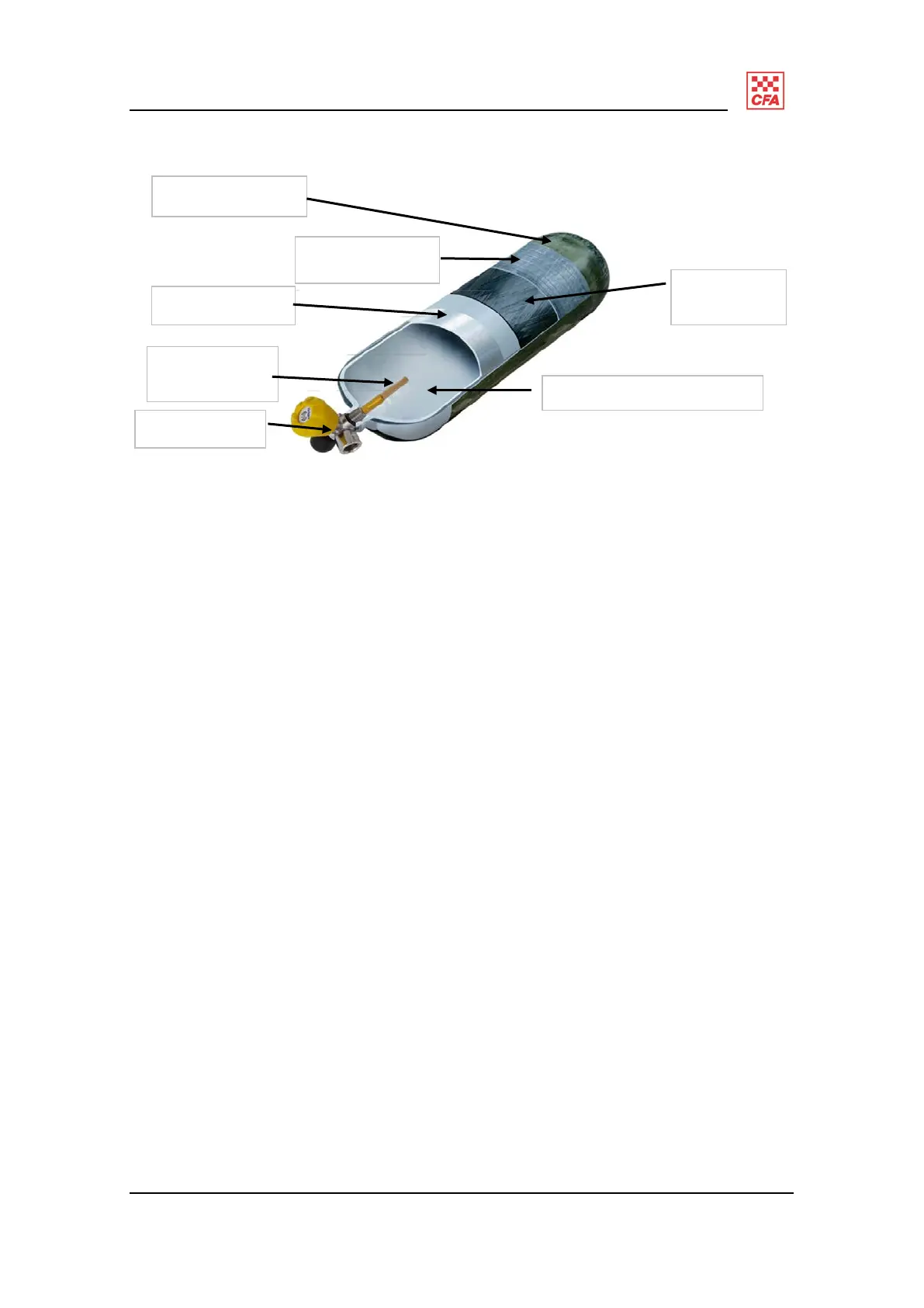
Figure 1: Dräger 300 bar cylinder and cylinder make-up
Cylinder and valve assembly
The cylinder and valve assembly stores high pressure air which will be reduced to
provide the operator with breathable air.
The valve assembly provides the operator the ability to open the pressure to the rest of
the system. The valve assembly consists of a handwheel for opening and closing the
valve and a threaded high pressure connection.
The 300 bar cylinder has a:
right angle valve;
ratcheting cylinder valve;
excess flow valve;
burst disc;
a vent hole in the threaded section to protect 200 bar pressure reducers from being
over pressurised; and
two passive radio frequency identification chips (RFID) for asset management
purposes.
The purpose of the excess flow valve is to reduce the rate of escaping air if required,
so that the cylinder does not become a projectile. It does not affect performance during
normal use.
Final resin layer
300 bar valve
Excess flow
valve/filter
Aluminium liner
Protexal anti-corrosion
layer
Carbon
wrap
Fibreglass wrap