Emotron VS Series Quick Start Guide
- 153 -
2) For PV power supply disconnect Q2, and then close Q1. For switching to grid or diesel engine
power disconnect the switch Q1, and then close Q2. Figure 2-4 show inter-locking connection between
connector KM1 and KM2, KM1 closed condition corresponds to PV power supply, whereas KM2
closed conditions corresponds to grid or generator power supply..
3) For grid or generator power supply, set y0.01=0.
4) If y0.01=0, then for water pump’s frequency, please refer to b0 group code. y0.02~y0.12 function
code will not work.
5) For changing to PV power supply, set C0.01=51 and close the terminal DI2 (or setting y0.01=1).
*Note:
It is recommended to install diode protection for PV input. If is not installed, PV panel
switch Q1 should be prohibited from closing together with grid power input switch Q2 to
protect the panel from damage
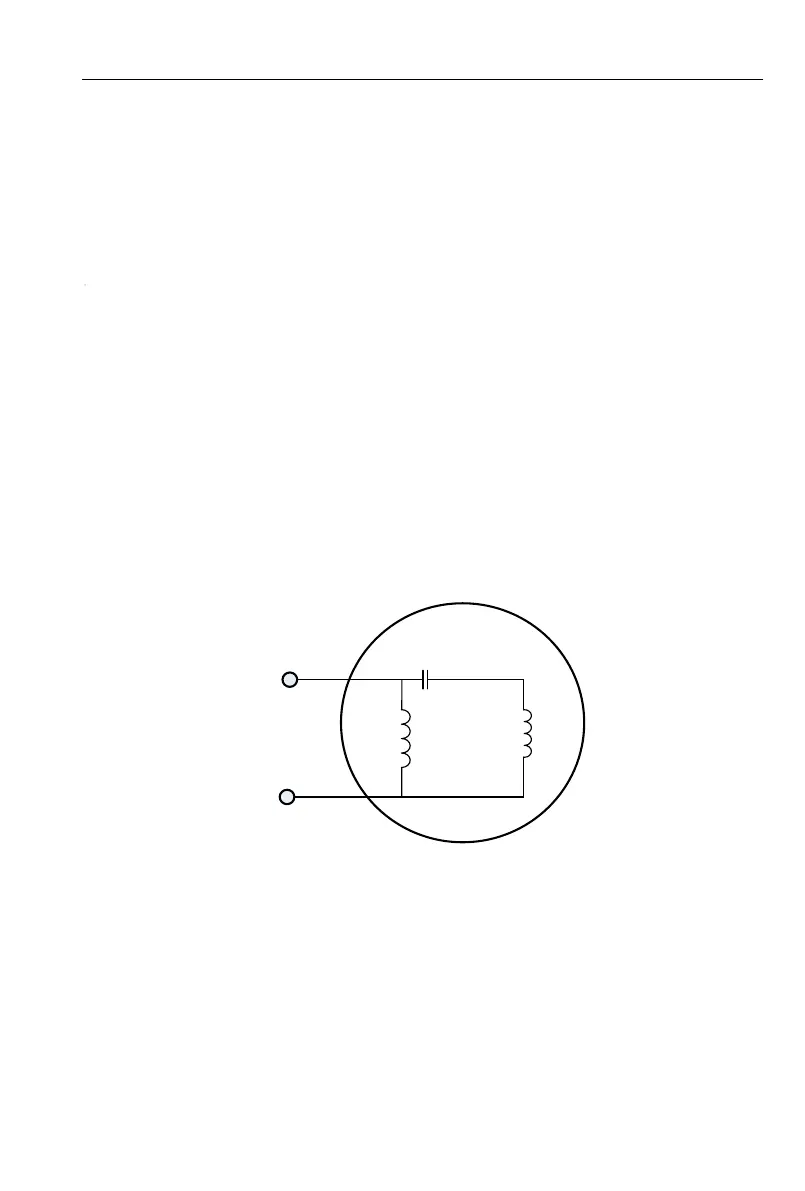
2. Wiring diagram between CG VFD and single phase motor
2.1 Single phase motor introduction
Single phase motor generally means asynchronous single phase motor powered by single phase
AC 220V There are two phase windings in motor stator and motor rotor is common squirrel cage. The
distribution of two phase winding and different power supply will lead to different starting
characteristics and operating characteristics
Usually single phase motor is with single capacitor or double capacitor. Single phase motor
consists of main winding, secondary winding, capacitor and centrifugal switch. Internal wiring of single
phase motor with single capacitor has been shown below
Main
winding
Secondary
winding
Starting
capacitor
U1
U2
Z1
Z2
M
220VAC
Fig 7-5 Operation mode: Internal wiring of motor with single capacitor
 Loading...