Emotron VS Series Quick Start Guide
- 25 -
3.5 Wiring Way of VS Series
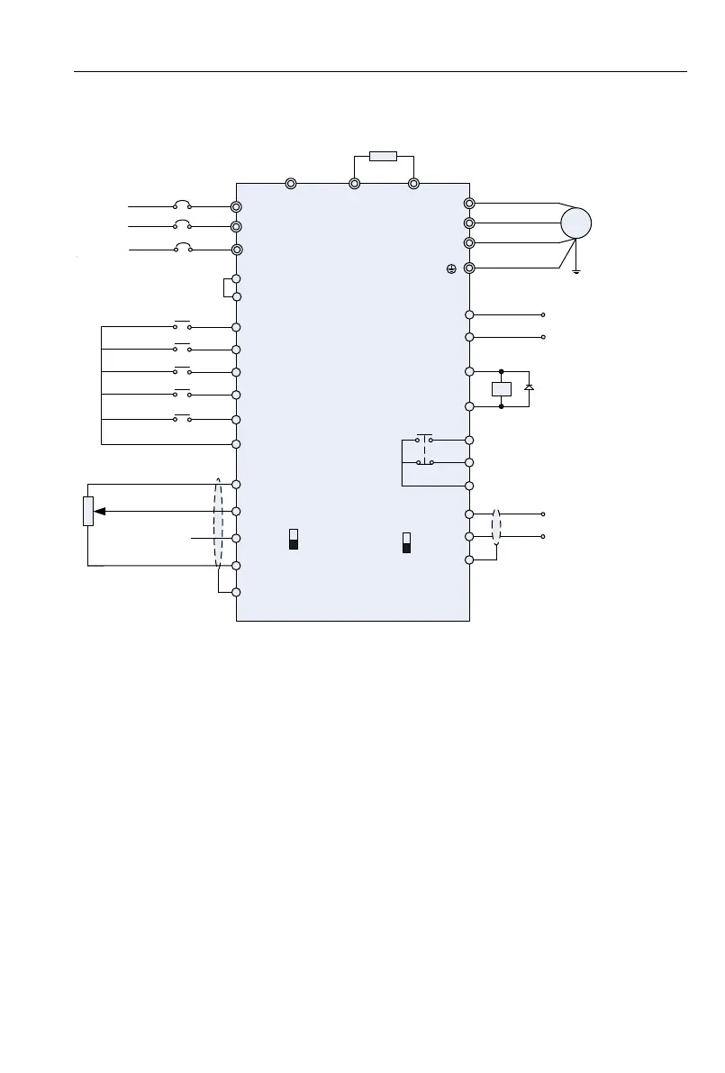
3.5.1 VSS, VSM , VSR(0.4~2.2kW) wiring diagram
L1
+24V
DI1
DI2
DI3
DI4
DI7/HI
GND
+10V
AI1
AI2
GND
PE
U
V
W
AO1
GND
485+
485-
GND
R1A
R1B
R1C
MCCB
1kΩ~5kΩ
DC 0~10V
DC 0~10V or 0~20mA
50/60Hz
Three-phase 415V
Single-phase 220V(L1, L2)
M
AI2
I
V
RS485
ON
OFF
(-) (+) PB
Braking resistor
24V
Y1
L2
Switch input 1
Switch input 2
Switch input 3
Switch input 4
High-speed
pulse input HI
Analog Output 0~10V
Open collector
output 1
Relay output 1
250V AC/3A
30V DC1A
RS485
Communication
PLC
L3
VSM
VSS
VSR (0.4~2.2kW)
Fig 3-7 VSS ,VSM ,VSR(0.4~2.2kW) wiring diagram
Remarks:
1)◎refers to main circuit terminals.,○refers to control circuit terminals.
2)User selects braking resistor based on real needs,Please refer to the braking resistor Selection
Guide.
3)Signal cable and power cable should be separated. Try to cross control cable and
power cable in 90° if needed. The best selection of analog signal lines shielded twisted pair,Power
cables use shielded three-core cable(The specifications of the motor cable than ordinary freshman
profile)or Comply with manual drive.
 Loading...