Emotron VS Series Quick Start Guide
- 18 -
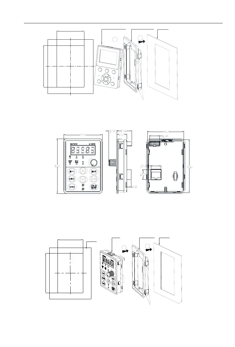
80
+0.2
-0
135
+0.2
-0
1
2
Keypad assembly
Keypad tray
Mounting plate
(The thickness of the
plate can`t be more
than 1.5 mm)
Press 4 hooks on both sides of the
mounting ,the keypad tray will be get out
LCD:Hole
size of mounting plate
Fig 2-8 LCD keyboard installation hole size diagram
2.5.2 VSS/VSR Series
Fig 2-9 Keyboard size diagram
External keyboard installation instruction:
1.first install the panel according to inverter’s power range corresponding to the size of hole as shown
on scheme 2-5, After that insert keyboard pad into the mounting panel and then insert the keyboard
module into the keyboard pad. (Before removing the keyboard pad, first remove the keyboard, then
remove the pad as shown in the scheme)
1
2
64
+0.2
-0
99
+0.2
-0
Keypad assembly
Keypad tray
Mounting plate
(The thickness of the
plate can`t be more
than 1.5 mm)
Press 4 hooks on both sides of the
mounting ,the keypad tray will be get out
Hole size of mounting plate
Mounting plate
Fig 2-10 External keyboard installation whole size diagram
 Loading...