M10 User Manual 11
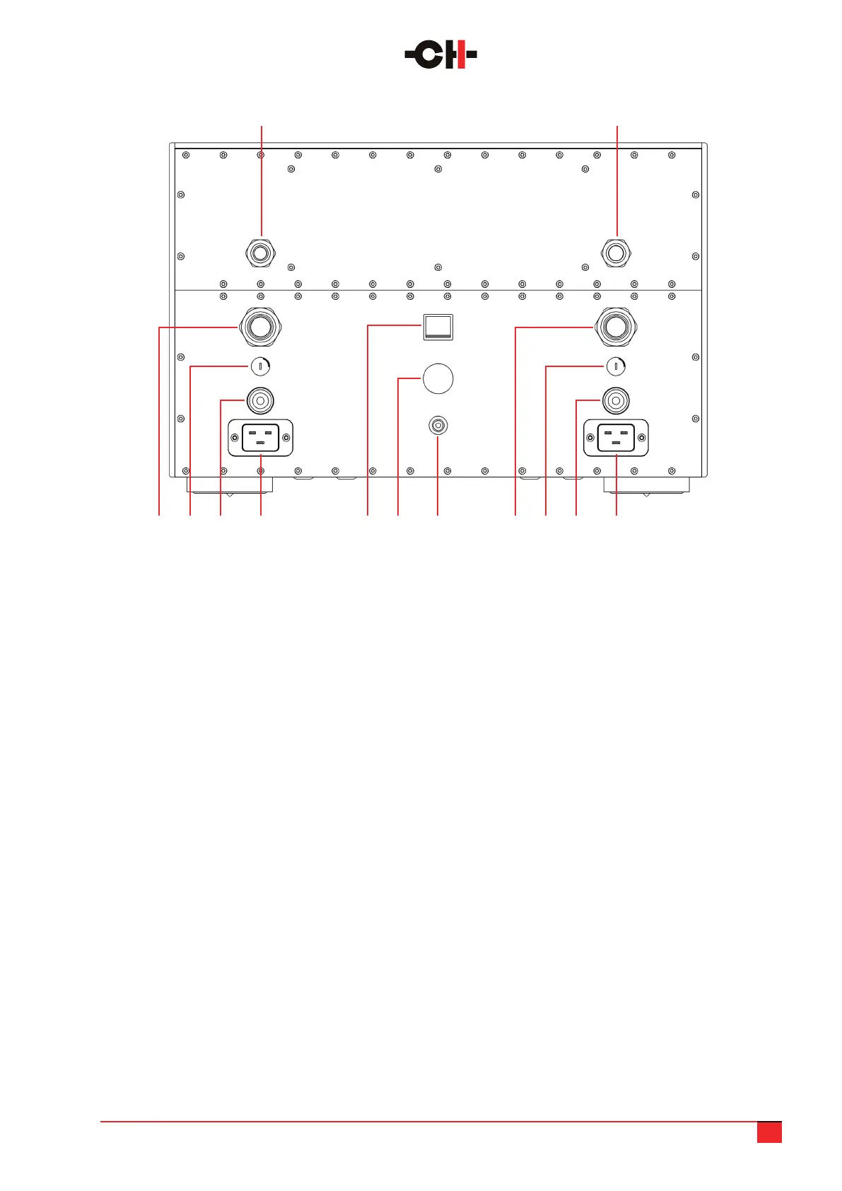
1. Control (digital) power supply umbilical cable,
to be connected to the corresponding socket in
the audio unit
2. Analog power supply umbilical cable, to be
connected to the corresponding socket in the
audio unit
3. Left 20A IEC power cord receptacle.
Both left and right need to be connected
4. Left high power section fuse (T10A for 230V
mains, T20A for 100V and 115V mains)
5. Low power section fuse (T1.6A for 230V mains,
T3.15A for 100V and 115V mains)
6. 2nd high voltage rail umbilical cable, to be
connected to the corresponding socket in the
audio unit
7. Earth socket. Internally connected to digital
ground and chassis
8. Mains voltage selector. Make sure it matches
your country’s power grid voltage
9. Mains power On/Off switch
10. Right 20A IEC power cord receptacle.
Both left and right need to be connected
11. Right high power section fuse (T10A for 230V
mains, T20A for 100V and 115V mains)
12. Standby section fuse (T250mA for 230V mains,
T500mA for 100V and 115V mains)
13. 1st high voltage rail umbilical cable, to be
connected to the corresponding socket in the
audio unit
You will note that as well as the array of conventional inputs and outputs, there are a number of other sockets
available which are used for control and update functions.
310 7 411 8 512 9 613
21
M10 power supply unit rear panel connections