K
Kevin PattersonJul 27, 2025
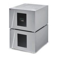
How to troubleshoot no power on CH Amplifier A1?
- BBrian MullenJul 27, 2025
If your CH Amplifier A1 has no power, first check the AC power cord. Then, check the power button located at the back of the unit. Finally, inspect the mains fuse on the AC power cord receptacle.