(11) XLR balanced analog output (pass-through for A1 chaining) for left channel [Left ANALOG_IN board]
(12) XLR balanced analog input for left channel [Left ANALOG_IN board]
(13) Transportation security screws (to be removed once A1 is placed in its definitive position)
(14) XLR balanced analog input for right channel [Right ANALOG_IN board]
(15) XLR balanced analog output (pass-through for A1 chaining) for right channel [Right ANALOG_IN board]
(16) Earth connector. Internally connected to digital ground
(17) Power fuse and voltage selection and power cord receptacle
(18) USB port for software upgrades. [CONTROL board]
(19) Argento Audio right negative speaker terminal
The CONTROL board is mandatory in any A1 configuration and is always factory installed. Depending on arrangement of optional
boards in the A1's expansion slots, connector arrangement may slightly differ on your unit. Each A1 unit provides 2 expansion
slots, each supporting a monaural analog input (ANALOG_IN) board.
ANALOG_IN boards provides 3 monaural user-selectable analog input connectors (balanced XLR, single-ended high impedance (Hi-
Z) / 300 Ohm RCA and BNC) as well as an XLR output monitoring the input signal. This output is used to daisy-chain multiple A1s
in multi-amplification systems.
Installation and removing of optional boards must be done by a qualified technician only. Do not attempt to install or remove any
optional board by yourself as this would void the unit's warranty.
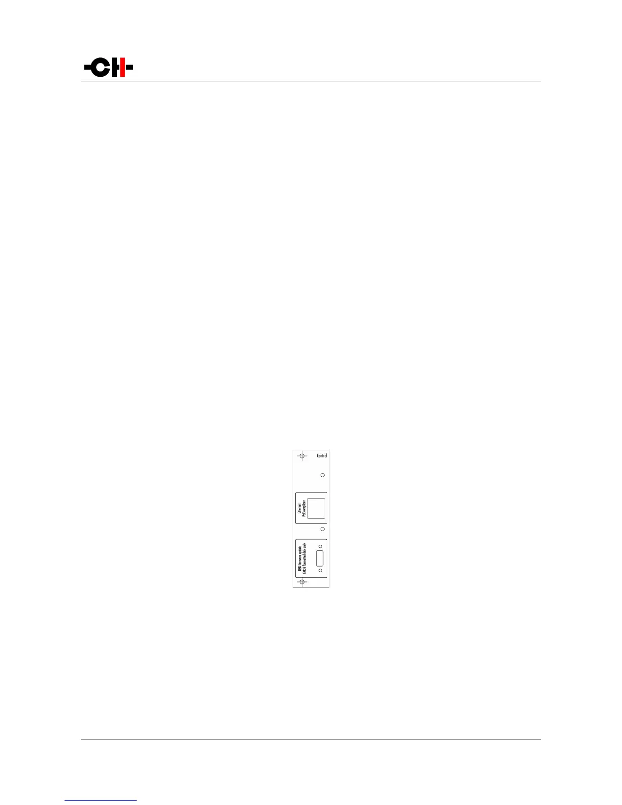
3.3.1 CONTROL board
The CONTROL board is factory installed into the A1. It provides a USB port for software updates and an Ethernet port for controlling
the unit over a network. Following drawing shows the layout of the back panel of the CONTROL board:
CONTROL board back panel layout
3.3.1.1 USB port
The USB port on the CONTROL board is dedicated to the firmware update of the A1 unit. Do not use it for any other purpose. For
more information on unit firmware update, please refer to the corresponding section of this manual.
18 A1 User Manual Rev 2.0