3.3.1.2 Ethernet port
The Ethernet port on the CONTROL board is dedicated to network based control of the unit. This functionality is currently not
implemented, thus leave the Ethernet port unconnected. A future A1 firmware release will provide this functionality.
3.3.2 ANALOG_IN boards
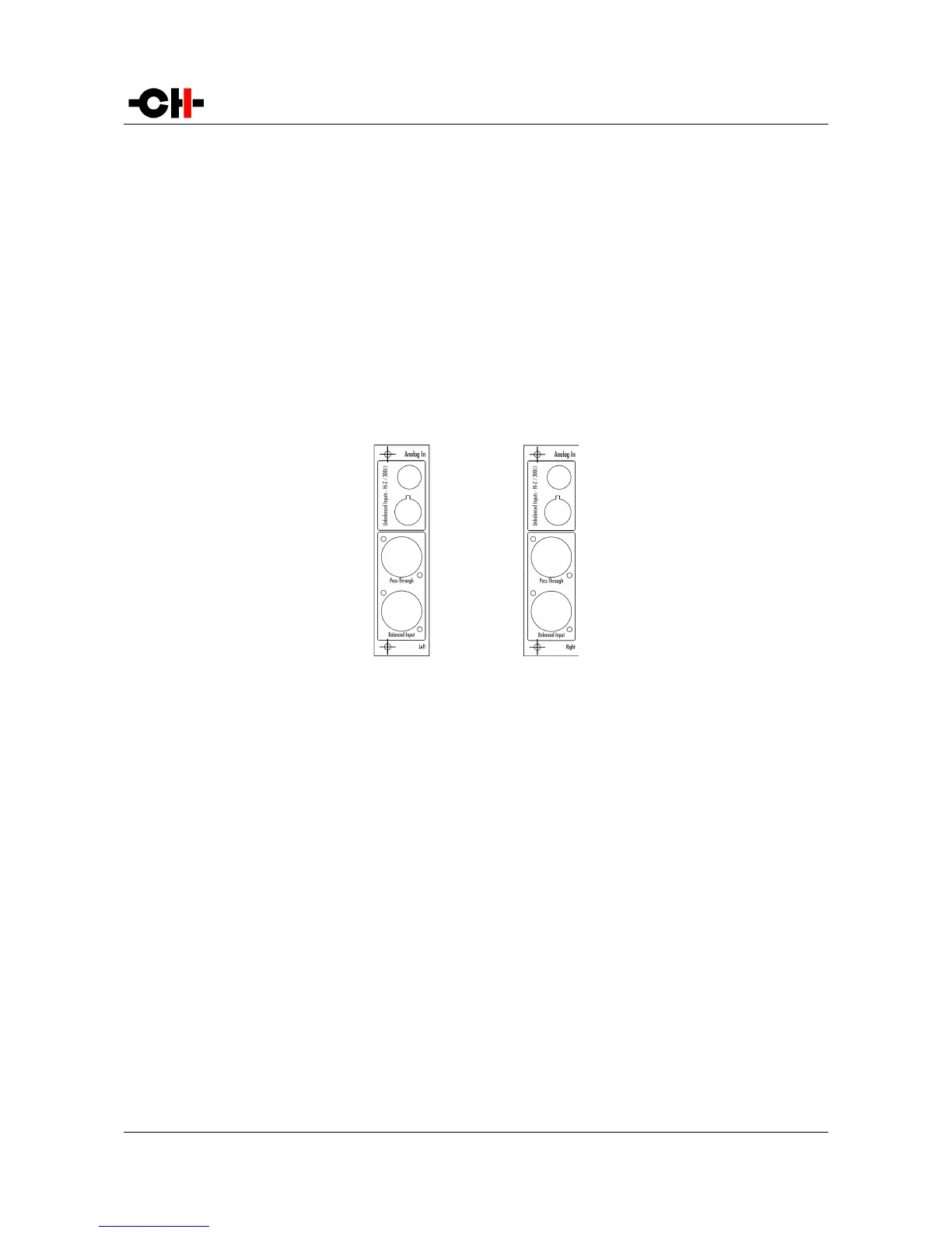
ANALOG_IN boards feature a user selectable mono analog input on three different connectors: single-ended RCA, single-ended
BNC and balanced XLR. The analog stage design is fully discrete and balanced. Both the RCA and BNC inputs can be configured for
high-impedance or 300 Ohms load, the later allowing for optimal signal transmission when connected to the outputs of 50 or 75
Ohm D/A controllers or preamplifiers. In addition to their inputs, ANALOG_IN boards include an XLR output providing a pass-
through of the input signal. This output can be used to daisy-chain multiple A1s in multi-amplification systems for ultimate
performance. Balanced connections are recommended for optimal performance. Following drawing shows the layout of the
connectors on the ANALOG_IN boards:
ANALOG_IN panel layout
3.3.3 Power cord receptacle and voltage selection
Make sure that the voltage selection is set to the correct value with respect to the AC voltage in your location. Connect the power
cord to the power cord receptacle and plug the power plug to an AC wall outlet only after all other connections have been made.
3.4 Amplifier modes
This section describes most standard setups in which one or multiple A1s can be integrated into.
3.4.1 Stereo mode
A single A1 equipped with two analog input boards can be used as a stereo power amplifier. This is the simplest configuration that
already allows to enjoy the unique sound of the A1 amplifier. The picture below shows how it should be connected in this case.
Rev 2.0 A1 User Manual 19