1.2.2 Temperature monitoring
The DSPs are also responsible for reading both the power transistors and the radiators temperatures. If the temperature gets
excessive, the class-A polarization is turned off, forcing the A1 to work in pure class-B. If removing the output stage bias current is
still not enough, and the temperature keeps rising, the A1 will protect itself by entering standby mode. Please note that under
normal conditions, none of the above should happen.
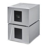
1.3 Mechanical construction
The A1 power amplifier is assembled from high-quality aluminum and steel elements with no visible screws on the front, top and
side panels. The front panel, base, side panels and top cover are machined from aluminum. The power supply is based on a fully
shielded 1200 VA toroidal transformer and custom rectifying capacitors sitting in the central position of the unit. Argento Audio
internal wiring is used throughout the unit and binding posts from the same manufacturer provide the best possible interface to
your speaker cables. The area where the air flows to cool down the amplifier is isolated from the rest of the A1, ensuring all
electronics are preserved from dust accumulation. Pin assembly of all chassis elements provides smooth joints between elements
while screws every 6cm ensures protection against electromagnetic interferences. First class mechanical and chemical surface
treatments provide the luxury finish of the A1.
Four steel feet support the unit. Each feet ends with a elastomer ring to sit on delicate surfaces but is also equipped with a height
adjustable steel spike to fine tune unit positioning. Horizontal adjustment is done with the provided screwdriver through the four
adjustment shafts accessible from the top of the unit. In addition to providing convenient horizontal adjustment from the top of the
unit, the shafts also serve as vibration evacuation channels for any stacked unit. Special shaft covers are provided to interface with
the spikes of the stacked unit. Any vibration from the upper unit is transmitted by the shaft cover to the shaft of the lower unit and
from there to the lower unit's feet or spikes, forming a privileged path for vibrations evacuation.
The area where the air flows to cool down the amplifier is hermetically sealed from the rest of the A1, ensuring the electronic
circuitry is protected from gradually gathering dust.
1.4 Modular architecture and slot-in boards
The A1 benefits from a fully modular architecture. It features separated sections for power rails, analog and digital power supplies,
front panel, signal routing and central host processor, monaural analog input boards and single channel amplification boards. This
modular architecture combined with the USB plug for firmware update allows for easy servicing and upgrade should one section
become faulty or obsolete.
The slot-in boards section consists in a vertically mounted mother board with optional boards plugged into it. Optional boards
provide audio functionality and connectivity to other equipment. There are two types of slot-in boards:
• ANALOG_IN: provides mono single-ended RCA and BNC (both configurable as either high impedance or 300 Ohm
terminated) and balanced XLR analog audio input. One (left or right) or two (left and right) such boards can be fitted
into the A1. By default, the A1 is factory delivered with a single ANALOG_IN board.
• CONTROL: provides a USB port for software upgrade and an Ethernet port for command. The CONTROL board is factory
mounted in each A1.
10 A1 User Manual Rev 2.0