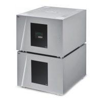
Shaft covers (left: stacking cover, right: top cover)
3.3 Connections
This section provides information about how to connect your A1 power amplifier to your system. As the A1 is a modular design with
different optional boards, the description applies to the example configuration presented below. For details about how to integrate
you A1(s) in a specific setup, please refer to the Amplifier modes section of this user manual. If you don't feel secure with the
connections to be applied to your configuration, please contact your authorized dealer for assistance.
The example configuration is a stereo-ready (2 input boards) power amplifier. Your configuration could only contain a single input
board.
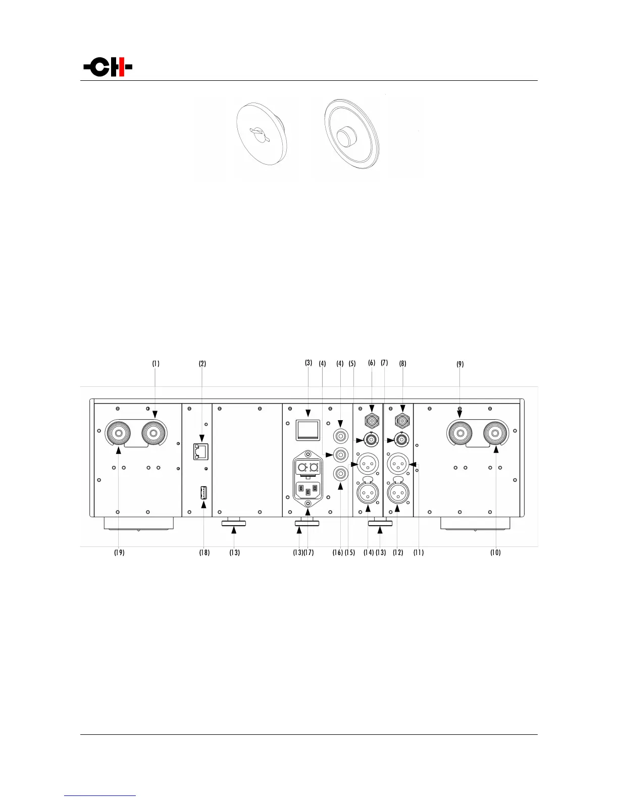
A1 rear panel connections
(1) Argento Audio right positive (or bridged mono positive) speaker terminal
(2) Ethernet port for command interface [CONTROL board]
(3) Power on/off switch
(4) Analog ground connectors. Bottom one can be connected to digital ground (Earth) using provided jumper
(5) RCA single-ended analog input for right channel [Right ANALOG_IN board]
(6) BNC single-ended analog input for right channel [Right ANALOG_IN board]
(7) RCA single-ended analog input for left channel [Left ANALOG_IN board]
(8) BNC single-ended analog input for left channel [Left ANALOG_IN board]
(9) Argento Audio left positive (or bridged mono negative) speaker terminal
(10) Argento Audio left negative speaker terminal
Rev 2.0 A1 User Manual 17